Inverter/Yoonseo Design: Difference between revisions
< Inverter
Jump to navigation
Jump to search
No edit summary |
|||
| (3 intermediate revisions by one other user not shown) | |||
| Line 1: | Line 1: | ||
=Overview= | =Overview= | ||
Youtube videos from Yoonseo on how the signals are transformed in the Inverter. | *Youtube videos from Yoonseo on how the signals are transformed in the Inverter. | ||
*[http://www.youtube.com/watch?v=QdNIinKLGW4&feature=plcp Inverter 101, Part 1] | |||
[http://www.youtube.com/watch?v=QdNIinKLGW4&feature=plcp Inverter 101, Part 1] | *[http://www.youtube.com/watch?v=4zAiwC5GQTY&feature=plcp Inverter 101, Part 2] | ||
[http://www.youtube.com/watch?v=4zAiwC5GQTY&feature=plcp Inverter 101, Part 2] | |||
=Modules= | =Modules= | ||
[https://en.wikipedia.org/wiki/Crowbar_%28circuit%29 Crowbar Circuit]: Short Circuit Protection (I'd have that on the DC side, right after the battery) | *[https://en.wikipedia.org/wiki/Crowbar_%28circuit%29 Crowbar Circuit]: Short Circuit Protection (I'd have that on the DC side, right after the battery) | ||
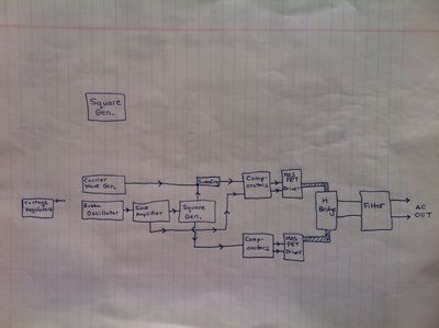
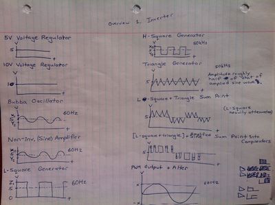
*Square Wave Generator | |||
Square Wave Generator | *Triangle Wave Generator | ||
*Reference Sine Wave Generator | |||
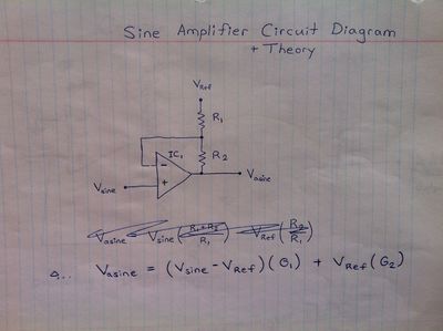
Triangle Wave Generator | *Sine Wave Amplifier | ||
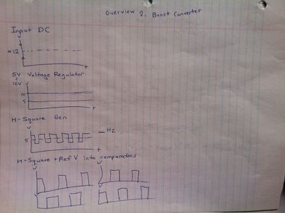
*[[Inverter/Boost_Converter Boost Converter]] | |||
Reference Sine Wave Generator | *[[Inverter/Push_Pull Push Pull]] | ||
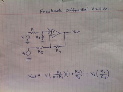
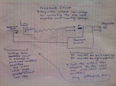
*Feedback (reference voltage chip and comparator) | |||
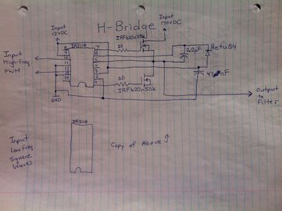
Sine Wave Amplifier | *[[Inverter/Yoonseo Design/H Bridge]] | ||
[ | |||
[ | |||
Feedback (reference voltage chip and comparator) | |||
== Notes on Inductive vs Resistive Loads == | == Notes on Inductive vs Resistive Loads == | ||
#Inductive loads use magnetic fields. Examples - Motors, solenoids, and relays. If it moves, it's probably an inductive load. | |||
#Inductive loads can cause blowback voltage. Circuits should be protected from this by diodes. | |||
#Blowback is caused by a surge of voltage created by the collapsing magnetic field in an inductor. | |||
#Resistive loads convert current into other forms of energy, such as heat. No risk of blowback. <ref> [http://www.markallen.com/teaching/ucsd/147a/lectures/lecture3/3.php] </ref> | |||
== Hand Drawn Schematics == | |||
== | |||
Note that WIkimedia sometimes does not find all the images, even though they've all been uploaded. If some of the images don't load, try reloading this page until the missing image appears. | Note that WIkimedia sometimes does not find all the images, even though they've all been uploaded. If some of the images don't load, try reloading this page until the missing image appears. | ||
| Line 46: | Line 34: | ||
[[File:03_Feedback_Differential_Amplifier.jpg|400px|thumb|left|Feedback Differential Amplifier]] | [[File:03_Feedback_Differential_Amplifier.jpg|400px|thumb|left|Feedback Differential Amplifier]] | ||
[[File:04_HBridge.jpg|400px|thumb|right|H Bridge]] | [[File:04_HBridge.jpg|400px|thumb|right|H Bridge]] | ||
Latest revision as of 23:01, 10 February 2018
Overview
- Youtube videos from Yoonseo on how the signals are transformed in the Inverter.
- Inverter 101, Part 1
- Inverter 101, Part 2
Modules
- Crowbar Circuit: Short Circuit Protection (I'd have that on the DC side, right after the battery)
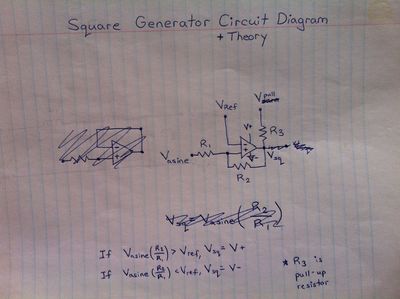
- Square Wave Generator
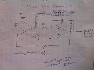
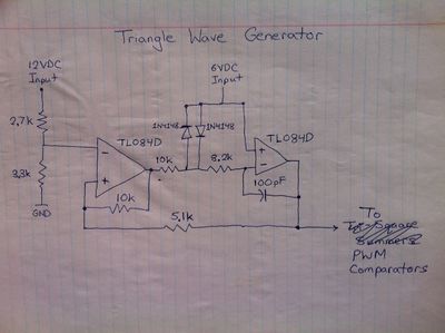
- Triangle Wave Generator
- Reference Sine Wave Generator
- Sine Wave Amplifier
- Inverter/Boost_Converter Boost Converter
- Inverter/Push_Pull Push Pull
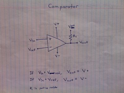
- Feedback (reference voltage chip and comparator)
- Inverter/Yoonseo Design/H Bridge
Notes on Inductive vs Resistive Loads
- Inductive loads use magnetic fields. Examples - Motors, solenoids, and relays. If it moves, it's probably an inductive load.
- Inductive loads can cause blowback voltage. Circuits should be protected from this by diodes.
- Blowback is caused by a surge of voltage created by the collapsing magnetic field in an inductor.
- Resistive loads convert current into other forms of energy, such as heat. No risk of blowback. [1]
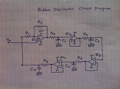
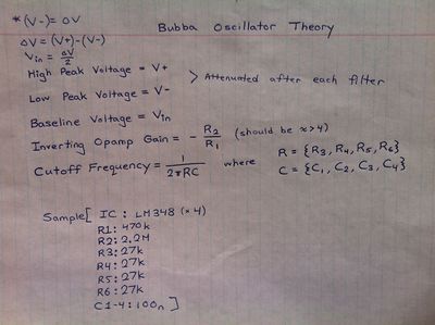
Hand Drawn Schematics
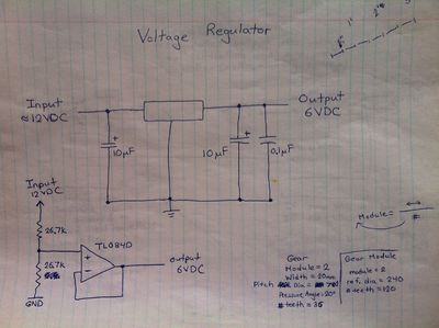
Note that WIkimedia sometimes does not find all the images, even though they've all been uploaded. If some of the images don't load, try reloading this page until the missing image appears.
