Jeremy Log: Difference between revisions
| Line 1: | Line 1: | ||
== '''February 7, 2020:''' == | == '''February 7, 2020:''' == | ||
Work on Pi tablet design and assembly concept mockup. [[File:PiFullCaseMockUp.png|100px]] See Parts Library or design Google Doc. | Work on Pi tablet design and assembly concept mockup. [[File:PiFullCaseMockUp.png|100px]] See Parts Library [https://wiki.opensourceecology.org/wiki/Part_Library_for_the_Raspberry_Pi_Tablet] or design Google Doc. | ||
== '''February 4, 2020:''' == | == '''February 4, 2020:''' == | ||
Revision as of 23:47, 7 February 2020
February 7, 2020:
Work on Pi tablet design and assembly concept mockup. 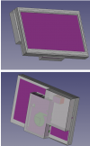 See Parts Library [1] or design Google Doc.
February 4, 2020:
More work on bezel + test print for fit.
February 3, 2020:
https://www.jeffgeerling.com/blog/2019/raspberry-pi-4-might-not-need-fan-anymore
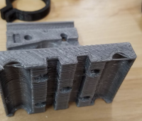
Drafted a bezel for testing screen fit. Updated size and fit for Piholder piece. Did some test prints for fit and alignment as initial draft did not account for pin height under the board.

February 2, 2020:
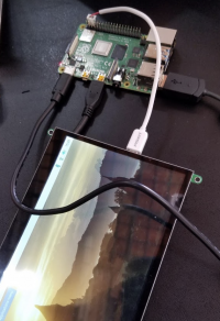
Power and USB alternate input to display on Pi Fablet attempted and verified. New Minor Problem: When Pi is shutdown from OS, Pin 4 still have 5v, so screen stays on until USB is powered off or disconnected. [Possible Work Around]
Uploaded a CAD mock-up for PiCase with notches/inset rear slots so that the important connectors can be accessed on the Pi. Mock-up includes an area for the forth coming OSE battery pack. Notes/thoughts in dev working document.
February 1, 2020:
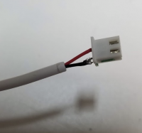
Worked on Pi Power issues. Discovered that screen (powered from Pi via USB) and Pi (powered from wall) would not load or power up. If they are each powered from a wall adapter, they boot normally. Tried using power from the 5v (pin 4)on the GPIO rail to run screen. Made USB cable (only power wires) to 2 pin connector (stole connector off old GPU fan). Routed this to pins 4 and 6. Both Pi and screen boot up right away. This seems the only way to power the screen from the Pi and reduce the incoming power cables from wall to case to 1.
NOTE: The USB cannot power the screen during BOOT, but was able to power the screen if the USB to screen was switched to Pi after BOOT.
Could also use a battery pack like [Battery Bank] and leave the charging port exposed and then use normal USB wires inside the case to power screen and Pi. Might be possible to modify Pi boot up to keep the USB off until OS is loaded, would not rely on a hardware hack to complete.
TL;DR: Found workaround for power issues, will reduce case size as well.
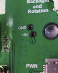
- TODO: Explore sending power directly from GPIO pin 4 to the 5v solder pad/test point on back of screen. This could eliminate all need for a USB power Line.
- TODO: Explore/Test USB solder pad to USB connector, may provide touch screen interface and power without using any USB ports on PI, making it easy to leave them at the edge of case and accessible. (this would require soldering these lines directly to the underside of the PiBoard on the correct pins, and may be a more involved solution than we are looking for, but still worth investigating)
Installed raspbian OS. Had some issues getting correct resolution on display. Manually set resolution in /boot/config.txt to 1088 x 600 (its 600x something odd... don't remember exactly). Very odd, but the stated native resolution left back side bars.
Printed of "L" carriage bracket for z-axis on D3D-U. The initial bracket not square. Planning to try to straighten, but wanted spare on hand.
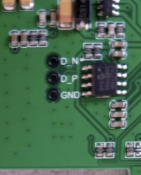
Ran multi-meter on solder pads(factory test locations?) on back of Pi display we have been working on. Confirmed that labels on board correspond to the correct pins on the USB circuit.
January 31, 2020:
Reviewed Pi wiring and layout on bench. Researched Pi pinout. [2]
Pi placeholder CAD parts for helping to determine optimal part assembly to minimize form factor of table. Pi Part Library Screen, PiHolder.
Made a couple fun replacement parts for an RC car that has been broken on my bench for a couple weeks. Fun exercise in free CAD. 
January 30, 2020:
Morning:
Worked on PiBase CAD. Not likely to be useful as some of the ports will be needed internally, but a good excercise in fully constrained drawings. ![]()
Researched Pi specs and screen interfaces and cabling.
Afternoon: Ran g-code generation in inkscape and sent to D3D. Printed updated fan/pen/prox holder for install at later date.
January 29, 2020:
Power Experiment Links: SlideDeck 1[3], wiki batterypack page[4], PowerPanel Wiki[5], Term. Block[6], Electrod Holder[7], Light Dimmer Slides [8] [9]
D3D Issue-O-Day:
Started printing plotter attachment and y-axis movement issues. Spend to long on troubleshoot. Ended up tweaking alignment of rails, and tracking down idler bearing not spinning freely. Also learned that the nozzle heat break fan is really good for ruining adhesion on the side of the bed its aimed at. Thinking future versions should move the air upwards, or possibly turn the fan off for the first few layers. Can we find a passive cooling solution?
Experiencing slight nozzle drag on nozzle moves. Is this an axis alignment issue, carriage free movement, or steps/mm? Read up on OS install to Pi, played with Pi parts like giant Legos... how best to fit together to achieve thin form factor.
January 28, 2020:
Researching wiki for current CNC mill progress, looking for previous CAD that is usable to attach to D3D-U. Found firmware info and spindle mount and Full working prototype from earlier D3D
Good Videos for FreeCad: Slicing parts from assemblies that are already created and have had their layers "flattened". FreeCad 0.18 PART WB using SLICE and SLICE APART FreeCAD of a simple screwdriver - drawn and printed.
Reviewed Arduino homemade documents and photos from Texas.
January 27, 2020:
Reviewed Wiki usage documents etc. Ran calibration prints and temp calibration print in D3D-U. Youtube tutorials on inkscape -> gcode. Pushed fresh install of mediawiki to sandbox server for learning purposes.
Sunday January 26:
Baby Step Calibration Procedure. D3D Universal Build Manual Calibration of D3D universal- Local. First Prints on FB Page
