Power Panel
Design
- STEAM_Camp_Module_Specifications#Universal_Power_Supply
- January_2020_STEAM_Camp#Day_4_-_Batteries_.2B_Welder_.2B_Power_Panel
CAD


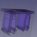
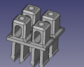
Terminal Block Module. - FreeCAD -File:Terminalmodule.fcstd. STL -File:Terminalmodule.stl
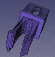
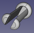
Power Panel Joint. - FreeCAD -File:Joint.fcstd. STL -File:Joint.stl
Power Panel assembly. - FreeCAD -File:Ppassy.fcstd. STL -File:Ppassy.stl
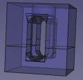
3D Printed Terminal Block - FreeCAD -File:Terminalblock.fcstd. STL -File:Terminalblock.stl
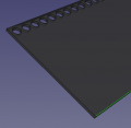
Power Panel - FreeCAD -File:Powerpanel.fcstd
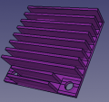
4040 heatsink. File:Heatsink.fcstd
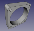
40x10mm fan File:40x10fan.fcstd
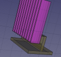
Power Module File:Powermodule.fcstd
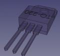
TO220 Transistor File:To220.fcstd
Quickpeg File:Quickpeg.fcstd. STL - File:Quickpeg.stl. Results: with 1.2 mm nozzle, feet break off easily. After breaking one, broke the second taking it off the printbed on D3D Universal. Going square.
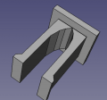
Quickpeg v2 File:Quickpeg2.fcstd. STL - File:Quickpeg2.stl.
Universal Power Panel Generator - FreeCAD File: File:UniversalPowerPanelGenerator.FCStd
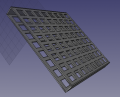
Universal Peg Array Generator -FreeCAD File: File:UniversalPegGenerator.FCStd
Universal Terminal Peg Generator File:UniversalTerminalPegGenerator.FCStd


Production Engineering Data Collection
- Challenging print regarding retraction due to ongoing hops
- Stringing is an issue
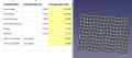
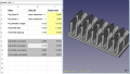
- On D3D Pro - D3D v19.11 6 - File:D3d1911 6.ini. But used 1.2 mm nozzle, 1.1 walls - keeps giving the double outer line upon slicing
- Weird artifact - only at 50-70% flow did it work (1.2 nozzle) - for some reason 100% flow spits out too much material. Never seen a case where flow rate had to be reduced to date. Settings in pertinent part:

BOM
Build
Terminals
Panel
CAD Notes
- 6 ga wire (50A) is 4.1 mm diameter. [1]
Applications
- Open Source Inverter - message to Paul Neelands:
Ideally, the spec would be:
- Division between Arduino Mega + LCD for the brains. We already use this elsewhere - https://wiki.opensourceecology.org/wiki/Universal_Controller. We use that in the 3D Printer and CNC torch table. It has an Arduino Mega underneath. Mega could also use touch LCDs so the interface is super simple.
- Separate power circuit.
- Power circuit is pure sine or as close as possible.
- It is done in modules of 500W or 1kW, so you can choose how much power you want - 1-10kW
- Modular transistor/heatsink assemblies - use one or as many as you want. Since we already use these fans and heat sinks and they work for 40W of power dissipation - can we find a 1kW power transistor that could work with these?
- Clamp-down bus-bar for DC input like the bus bars in breaker boxes so we can attach as many gauge 6 or 4/0 feed cables as needed.
- By default, that would make the above stackable if we have multiple power stages - and a single brain.
- Design the system for 24 or 48V input - and once you do that, we can work out components for other voltages if needed. Ideally, the same system would work from 12-120v or such, and the adaptation to the voltage would happen in software.
- Design with algorithm for NiFe batteries. For the next Seed Eco-Home, our likely candidate will be either 24V 100Ahr NiFe or 48V 100 Ahr NiFe.
So the idea is - the Arduino Brain can drive 1 to as many IGBTs as needed for as much power as needed. The Mega has 52 IO pins or so, so easily 52kW max for scalability if we use 1kW power elements.
Then we use power modules - initial concept like this - https://wiki.opensourceecology.org/wiki/File:Powermodule2.png
The page on the wiki is https://wiki.opensourceecology.org/wiki/Power_Panel = basically - a 3D printed plastic panel, and you snap in whatever compoements. Gauge 6 terminal blocks come from screwing in 1/4" screws or 6 mm screws.
That's a concept only- general drift. Imagine: anyone could follow a basic design guide and create an inverter based on the design guide and reference circuits, all open source with KiCad and FreeCAD. The value proposition is Lifetime Design. What do you think? Marcin
Links
 Open Source Inverter - includes the scalable power module
- 3D Printed Terminal Block