Industrial Robot/Manufacturing Instructions: Difference between revisions
Jump to navigation
Jump to search
No edit summary |
|||
| Line 70: | Line 70: | ||
=Fabrication= | =Fabrication= | ||
===[1] Base Plate=== | ===[1] Base Plate=== | ||
| Line 181: | Line 139: | ||
*Correct image dimensions to 10" by 6" instead | *Correct image dimensions to 10" by 6" instead | ||
==Stepper Mount== | ==Stepper Mount== | ||
| Line 423: | Line 158: | ||
[[Media:StepperMotorMountPlate.jpg]] | [[Media:StepperMotorMountPlate.jpg]] | ||
===[6] Shaft | ===[6] Shaft Coupling=== | ||
**Mark cuts with scriber and box-square | **Mark cuts with scriber and box-square | ||
**Cut with torch cutter | **Cut with torch cutter | ||
| Line 431: | Line 166: | ||
[[Media:ShaftBar.jpg]] | [[Media:ShaftBar.jpg]] | ||
==Assemble Stepper Motor Mount== | ==Assemble Stepper Motor Mount== | ||
| Line 447: | Line 171: | ||
*As shown below, repeat for a total of 6 mounts | *As shown below, repeat for a total of 6 mounts | ||
[[Media:Stepneedlemount.jpg]] | [[Media:Stepneedlemount.jpg]] | ||
==Electronic Connections== | ==Electronic Connections== | ||
| Line 467: | Line 180: | ||
[[Category:Industrial Robot]] | [[Category:Industrial Robot]] | ||
Revision as of 19:50, 3 September 2011
| Industrial Robot | ||
|---|---|---|
| Home | Research & Development | Bill of Materials | Manufacturing Instructions | User's Manual | User Reviews | 
| |
Tooling and Infrastructure
Measuring and Marking
- Scriber
- Try-square
- Box-square
- Metal Rule
- Combination Set
- Center Punch
- Nipple Punch
Taps and Dies
- 1/2" - 13 Taps
- 9/16" - 18 Taps
- Tap Wrench
Port Cutting
- SAE6 Port Contour Cutter
Drilling
- Cordless Drill
- 1/2" drill bit
- 3/8" drill bit
- 1/4" drill bit
- 5/32" drill bit
- 1/8" drill bit
Soldering
- Soldering Iron and Stand
- Solder
Torching
- Oxy-acetylene Torch
Turning
- Lathe
- Cutting tools - turning, grooving
Hand Tools
- Adjustable pliers
- File
Fabrication
[1] Base Plate
- Mark drill points with scriber, combination set, and center punch
- Drill with cordless drill or drill press
- Smooth with file
- (new image TBD)
[1] Main Arm
- Mark 2" dia. hole centers with scriber, combination set, and dot punch
- Mark 2.5" dia. and 2" dia. hole circumferences with divider, rule
- Mark 1/2" dia. hole centers with divider, rule, center punch
- Cut 2" dia. holes with torch cutter
- Drill 1/2" dia. holes with 1/2" twist drill bit and cordless drill
- Remove burrs around holes with file
Forearm
[1] Perpendicular Plate
- Mark 2" dia. hole center with scriber, combination set, and dot punch
- Mark 2.5" dia. circle with divider, rule
- Mark 1/2" dia. hole centers with divider, rule, center punch
- Cut 2" dia. hole with torch cutter
- Drill 1/2" dia. holes with cordless drill
- Remove burrs around holes with file
- Weld to "Forearm Tube" with welder
[1] Parallel Plate
- Mark 2" dia. hole center with scriber, combination set, and dot punch
- Mark 2.5" dia. circle with divider, rule
- Mark 1/2" dia. hole centers with divider, rule, center punch
- Cut 2" dia. hole with torch cutter
- Drill 1/2" dia. holes with cordless drill
- Remove burrs around holes with file
- Weld to "Forearm Tube" with welder
- Correct image dimensions to 10" by 6" instead
Stepper Mount
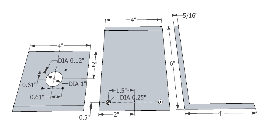
[6] Stepper Motor Mount Angle
- Mark cuts with scriber and try-square
- Cut with torch cutter
- Mark holes with scriber, rule, try-square, and center punch
- Drill holes with 1" bit, 1/4" bit, 1/8" bit, and cordless drill
Media:StepperMotorMountAngle.jpg
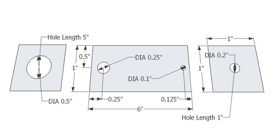
[6] Stepper Motor Mount Plate
- Mark cuts with scriber and try-square
- Cut with torch cutter
- Mark holes with scriber, rule, try-square, and center punch
- Drill holes with 1/4" bit and cordless drill
Media:StepperMotorMountPlate.jpg
[6] Shaft Coupling
- Mark cuts with scriber and box-square
- Cut with torch cutter
- Mark thru hole with scriber, combination set, and center punch
- Drill holes with 1/2" bit, 1/4" bit, 5/32" bit, and cordless drill
- Tap holes with 10-24 taper/intermediate/plug taps and tap wrench
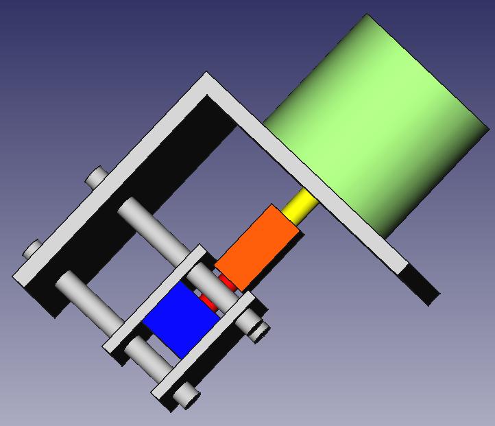
Assemble Stepper Motor Mount
- As shown below, repeat for a total of 6 mounts
Electronic Connections
- Solder solenoid driver Instructions
- As shown below