Steam Engine Design/Free Piston Steam Hydraulic: Difference between revisions
| Line 6: | Line 6: | ||
This engine's pulsating hydraulic output would be directed to a hydraulic accumulator in a typical [[Stationary_Hydraulic_Power | stationary hydraulic power]] installation. | This engine's pulsating hydraulic output would be directed to a hydraulic accumulator in a typical [[Stationary_Hydraulic_Power | stationary hydraulic power]] installation. | ||
See some other free-piston references [[Steam_Engine_Design/Suggestions#Crankless_.28Free_Piston.29_Hydraulic | here]]. | |||
---- | ---- | ||
Revision as of 11:59, 21 November 2011
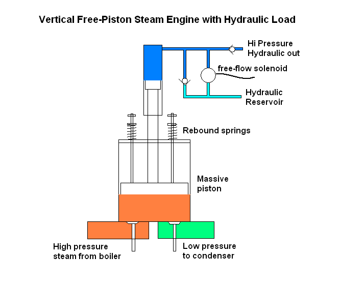
Free Piston Steam-Hydraulic Engine
Intake and exhaust poppet valves operated electrohydraulically.
This engine's pulsating hydraulic output would be directed to a hydraulic accumulator in a typical stationary hydraulic power installation.
See some other free-piston references here.
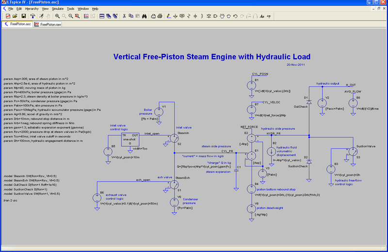
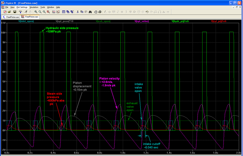
Simulation model using freely available LTSpice IV simulation program. LTSpice is intended for electrical schematics, so it labels everything as volts and amps. However the simulation math doesn't care whether we are voltage or pressure or mass.
This code is a "first cut" and is missing several friction/loss mechanisms. It also lacks a lookup table for wet steam behavior. Feel free to exercise the model with different parameter values (for many you can just edit the .param lines) and to add improvements. Steam_Engine_Design/Free_Piston_Steam_Hydraulic/SpiceCode


