Jonathan Kocurek Log: Difference between revisions
| Line 200: | Line 200: | ||
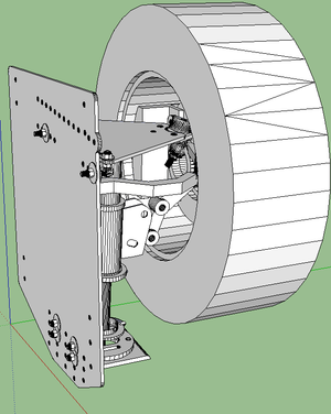
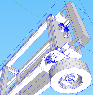
Dave and I worked on getting the PowerCube Modules guts to fit into a 4x4" tube frame and attach it to the articulated steering pivot and the rear wheel base. | Dave and I worked on getting the PowerCube Modules guts to fit into a 4x4" tube frame and attach it to the articulated steering pivot and the rear wheel base. | ||
[[File:LifeTrac_Pivot.jpg|300px]] | [[File:LifeTrac_Pivot.jpg|300px]] [[File:WheelBase.jpg|300px]] [[File:LifeTrac_w_Wheelbase.jpg|300px]] | ||
[[File:WheelBase.jpg|300px]] [[File:LifeTrac_w_Wheelbase.jpg|300px]] | |||
=Thurs 8/8/2013= | =Thurs 8/8/2013= | ||
Revision as of 18:23, 23 August 2013
Permanent Links
LifeTrac 6 Production Requirements
LifeTrac 6 Product Development Board
Master Product Development Board
Product Concept & Key Performance Parameters Template
DPV Orientation and Message Board
Collaborators' Logs
Fri Aug 23, 2013
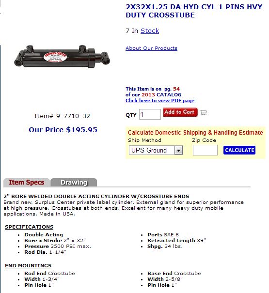
Arm Cylinder Specs
Thurs Aug 22, 2013
Up to date version of File:LifeTrac6.skp
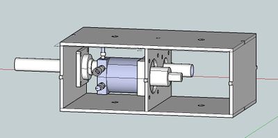
I worked on the new gearbox assembly and here's a rough idea of what it will look like.
STL Import for Sketchup
I've been having real trouble importing files from AutoDesk Inventor into Sketchup. I finally figured out a pretty easy way to do it using STL files.
- Save your part (or assembly) from Inventor or SolidWorks as an STL file.
- Go to Sketchup and click File:Import and choose the .stl file type.
- Click the Options button and check the box that says "Merge Coplanar Faces"
- Choose the units you used to draw the part file in the other CAD Program.
- Close the Options window and open the .stl file you saved.
- The part will load, but the measurements will NOT equal the part you drew in the other CAD program.
- As long as you have access to the original dimensions, it's a simple proportion formula.
- Measure a corresponding dimension on the part in both programs.
- To find the scale you should use to edit the Sketchup part, use: (Sketchup Dimension / Other CAD Dimension) = X
- Select the whole part in Sketchup and use the scale tool
- Type the value you found for X in the dialog box.
- Voila! Your part matches in both programs.
Wed Aug 21, 2013
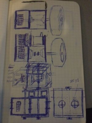
Discussion on wheelbase with James and Gary. Current LifeTrac design has ~8' wheelbase. This is extremely hard to get on a trailer. Wheelbase hasn't been narrowed so far because the modular gearbox design is all in line with the drive shaft. There isn't much room to be had without making drastic changes. Gary has put me in charge of re-designing the modular gearbox to allow more room to narrow the wheelbase. I have a pretty good idea of what it should look like already. I drew up some sketches on paper that you can see here - might not make too much sense, but I should have the CAD file done by tomorrow, maybe Friday.
Tues Aug 20, 2013
Worked with James Slade on CEB presses in the shop. Some bolt holes don't line up so we've been cutting new holes to fit everything right. Still got a way to go.
Mon Aug 19, 2013
Sun Aug 18, 2013
Sat Aug 17, 2013
Worked a lot on CAD for the tractor loader arms. Dave discovered before he left FeF that some bobcats and other tractors use only one well mounted cylinder in the front and two in the back that lift the arms. I played with that and found a config that looks like it should work well and it looks pretty awesome. Found a cylinder for the front articulation that fits my design perfectly! Also helped James with some lifting and moving on the CEB Presses to be used for the MicroHouse build.
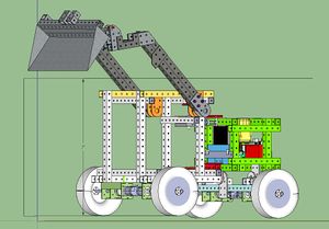
Still working on narrowing the wheel base. James says that we cannot have it as wide as it is because it won't fit on a trailer. I'm thinking of modifying the quick attach gear-shaft housing to allow some more room. Will update soon.
Fri Aug 16, 2013
In our presentation yesterday we talked about a few things that OSE processes lack:
- System Simulation and Testing
- System Validation and Verification
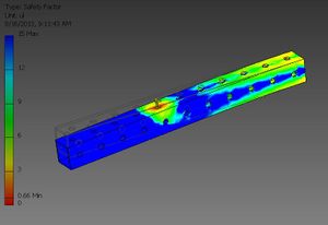
In OSE's current design process there is no easy way to model even the simplest kinematic motions in google Sketchup let alone the stress analyses, load transfers, torque, hydraulic power, and other physics required to develop a quality machine. META tools has the potential to solve all of these problems and more for an organization with an open source library of components. But right now, current CAD software has the ability to model and simulate at least the mechanical side of the design. Specifically, my productivity in the design process speeds up significantly with the ability to perform finite element analysis and constrain rotation and piston extensions. Google Sketchup does not currently have these tools available.
Since I'm a current student at BYU, I have access to the free educational versions of much more powerful CAD programs. I'm most adept at AutoDesk Inventor Professional, but SolidWorks, Creo, and Catia are all much more useful than Google Sketchup and there are ways to convert files to and from free platforms.
Since OSE is an Open Source community, I'm sure they can apply for and receive licenses for educational programs. From what I've seen, DPVs who come to FeF are most often college students anyways, (and many remote collaborators are too) so using a free educational version of CAD software wouldn't be out of the question. I'm not advocating phasing out google sketchup altogether. But for the more advanced design and structural analysis, I think using these more powerful programs will help OSE tremendously with its limitations to simulate and test their models.
File:OSE Meta Presentation.pptx
Thurs Aug 15, 2013
Developed executed, and filmed a META Tools presentation. OSE leadership seemed impressed and very excited about future collaborating opportunities with ISIS, Vanderbilt, and BYU. More on that later.
Wed Aug 14, 2013
Reformatted cab, front wheelbase and loader arm width to symmetric centered configuration again. Material savings in asymmetric config was only 32", we decided it was much more professional looking and mechanically balanced this way.
I have noticed that in the weekly design sprints, several things were missing that were essential to gain traction:
- Visual Representation of ideas discussed
- Proper Documentation of the Meeting
- Designated project leadership and project team organization that translates the issues discussed by Marcin into value added time during the design sprint.
I discovered a very neat new tool for online collaboration groups that can help solve these three problems. Vyew is a web-based conferencing application that’s free to use for up to 20 participants per conference room. Collaborators can upload and share files, pictures, MS Office documents, PDFs, and screen share, annotate, edit and download. Conference Rooms never close, so the discussion board is saved for future use and can serve as documentation for the meeting. Discussion can extend to multiple pages with sections for organization.
Here's some ideas for how to use it:
- Marcin, DPVs and Factor e Farm employees prepare the conference room with visual representations of critical issues to discuss.
- One page per design topic (IE per machine)
- Once the collaborators arrive, they must be:
- briefed on the issues,
- assigned to a project leader,
- and separated into a different Vyew conference room with their team to engage in the design sprint.
Tues Aug 13, 2013
Marcin came in today and we talked about what Design Requirements are needed for the Loader Arm. I've been trying to draw up a way to document these design requirements for each module included in the LifeTrac. So far, I've just been creating Google Drawings of the module design requirements. I provided a link to edit the drawing and a visual representation of it to the LifeTrac 6 Modules page. That way whenever the drawing is updated, the visual representation should also update on the wiki.
I discovered that sometimes the visual representation doesn't always update in real time. If that happens, it's because your internet browser's cache has to be deleted.
Mon Aug 12, 2013
We had a meeting with Marcin and Katie today about work progress. For the past week, the tractor design team has been making changes on the various modules that comprise LifeTrac 6. Several team members are new arrivals (including myself) and have trouble tracking down the knowledge required to make educated decisions on how to proceed on the LifeTrac. Traction for newcomers requires 3 important things:
- A set of operational definitions
- Design Requirements
- A centralized repository of relevant information from past workers
I have set out in an effort to fill in some of the gaps in these elements.
Important Orientation Elements for Newcomer Designers
Operational Definitions - First is to create a universal nomenclature for the hardware pieces we are working with.
Design Requirements - Marcin and the team worked together today to nail these down.
Design Repository - I created a LifeTrac 6 Modules Page where the most current screenshots and .skp files are located on the modules needed to build the tractor. Also it shows concept art and names of parts.
Sun Aug 11, 2013
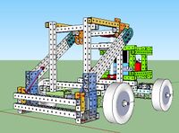
With only two sets of actuators, and the design rules I am aware of right now, this is the best configuration I've been able to draw up.
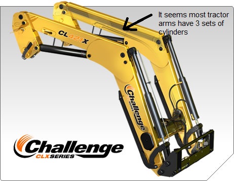
It seems that some tractor arms have 3 sets of actuators for a larger range of motion. Should we explore this?
PowerCube contents fit very nicely inside the 4x4 tubing config.
File:PowerCube Guts in 4x4.skp
Sat Aug 10, 2013
We made significant progress on the tractor loader design and interface with the cab. As of now, the bucket can dump at a 45 degree angle when the bucket tip is above 7' from the ground. I've tried many many configurations to try to follow the design constraints given us, namely that the bucket must dump at 60 degrees when the tip is @ 7' and have the bucket able to dig 1' below the ground when the bucket is flat and the arms are at rest. So far, I haven't figured out how to do all of those. The current version seems to be a possibility. If the bucket can clear the 7' CEB hopper height and dump down into it while lowering the arms I think this current version will work fine.
Fri Aug 9, 2013
Dave and I worked on getting the PowerCube Modules guts to fit into a 4x4" tube frame and attach it to the articulated steering pivot and the rear wheel base.
Thurs 8/8/2013
Wed 8/7/2013
I finished the 36” stroke hydraulic arm and drew up a new frame for the PowerCube. I used 36” 4x4” tubing for the outside cube frame, creating an open cube space interior of 28x28x28”. I also went down to the shop to inspect the existing PowerCube with the angle iron frame. The outer dimensions of the angle iron frame are ~30x30x30”. The interior guts do not fit exactly within 28x28x28, but with minor modifications on a new model, they can be made to fit.
Lucas briefed Dave, Scott and I on the to do tasks on updating the LifeTrac. We will be changing the loader arms, the PowerCube frame, the articulated steering pivot, the ground-hugger pivot, and the width of the wheelbase and cab.
Tues 8/6/2013
This morning Lucas had me work on drawing up a hydraulic arm in sketchup. I won’t lie, sketchup is definitely not as powerful of a program as I’m used to, but I’m learning it. The hydraulic arm model will be used as a measurement tool in the latest version of the LifeTrac Tractor.
The 3D printer we worked on last night needed to be re-calibrated again today. We used a more accurate measurement system - an indicator dial - to ensure the nozzle had flat printing plane on the printing board.
In the afternoon, Lucas had me do another hydraulic arm, this time at a 36” stroke.
Mon 8/5/2013
I came into Kansas City today by Greyhound Bus. Since my phone died on the way here, I was unable to confirm the time which I needed to be picked up. Luckily when I arrived, there was a way to charge my phone and contact Scott, who came to get me. After traveling back to Maysville, MO, I unloaded my things and took a tour of the facilities. The shop looks quite impressive. I met the other Dedicated Project Visitors: Jon, Dave, and Lucas.
Jon has been having trouble with the 3D printer that will be used in the design of the HydraFabber. The extruder nozzle would not line up properly with the building board and thus not be able to print. At first, we thought to level the board and test the nozzle by eyeballing it as we moved it left and right. After some time, we realized the real problem wasn’t the base board, it was the rails that supported the nozzle that were at an angle. After adjusting the Z-Axis threads to match each other, the process was simple to get it to print.
Sat Jun 1, 2013
Converted SGT01 Wikispeed car STEP files into Sketchup.
