Module Breakdown - MicroHouse: Difference between revisions
| Line 76: | Line 76: | ||
Pouring the concrete for the MicroHouse foundation: | Pouring the concrete for the MicroHouse foundation: | ||
<html><iframe width="420" height="315" src="//www.youtube.com/embed/9zqPdDvIptg" frameborder="0" allowfullscreen></iframe></html> | <html><iframe width="420" height="315" src="//www.youtube.com/embed/9zqPdDvIptg" frameborder="0" allowfullscreen></iframe></html> | ||
Revision as of 14:22, 19 March 2014
The MicroHouse is broken into modules to enable a social production model like all OSE machines/architecture.
Foundation Module
Development
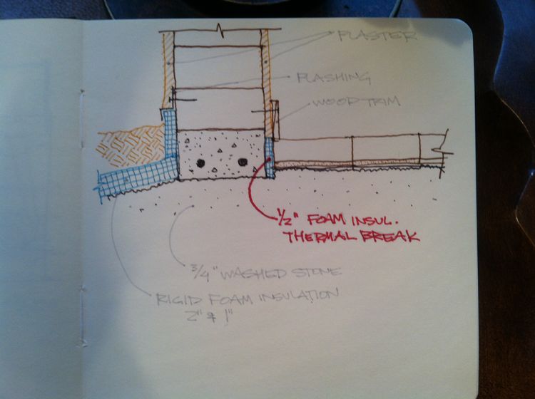
This early drawing explored a stemwall idea for the MicroHouse foundation and looked at various ways of insulating the foundation and siding the building.
Marcin was very interested in continuing to experiment with the shallow insulated footer concept. Here is a drawing based on design discussions between Floyd and Marcin. More information about the shallow insulated footer concept can be found here.
Based on conversations with Walter Grondzik, PE... One item we discussed was getting the best performance from the direct solar gain heating system (heating of the CEB floor by sun shining through windows). Walter highly recommended putting in a thermal break between the floor and the foundation. Without this break, there heat will travel easily from the floor to the foundation. He suggested a 1" thick piece of foam, but he agreed that a 1/2" piece would be acceptable. Even at 1", the plaster and a trim board would cover it.
Here was the initial idea for foundation formwork, discarded in favor of the simpler, faster idea presented below in execution section.
Execution
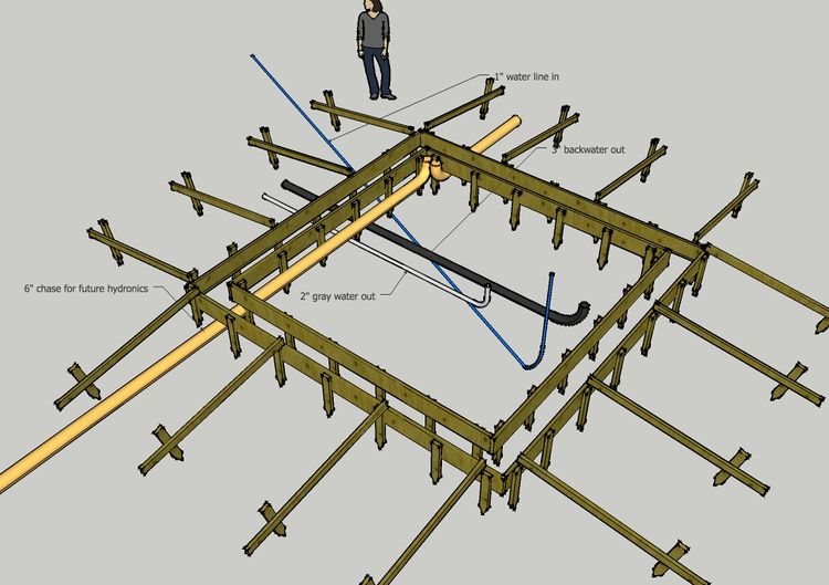
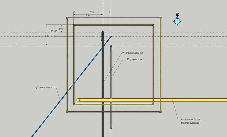
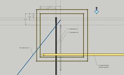
Precise dimensions for pipe layouts
Notes:
  1. Measure and mark opposing interior form boards with dimensions listed.
       1a. Measure from outside of inner form board (in other words, from what will be inside of concrete).
  2. Put small nail into form top at location of mark - string between similar mark on opposing form board.
  3. Run designated pipes under foundation formwork and make sure vertical pipe is directly under
     proper intersecting strings.
  4. 6" chase for future hydronics does not need to be at any slope.
  5. 2" graywater and 3" blackwater lines MUST BE AT 1/4" slope per 1' of length.
     This is required for proper drainage, otherwise liquids will outrun solids.
  6. Pipe layout shows 6" chase running over 2" and 3" lines, however, it is typical to conserve as much
     elevation as possible when exiting graywater pipes... best practice will be to run 2" and 3" pipe
     out just below bottom of foundation formwork. 6" pipe will most likely run beneath level of 2" and 3" pipes.
  7. Run pipes past foundation forms by roughly 5' and cap with cardboard/duct tape or old rag, etc.
     Leave vertical pipes at a length of 1' taller than foundation forms. Cap this end, as well.
     Staking the vertical pipe in place with rebar will prevent it from getting disturbed.
Pipe Elevations:
Instructions Sketches
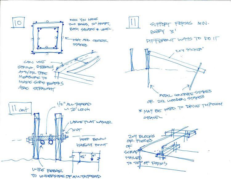
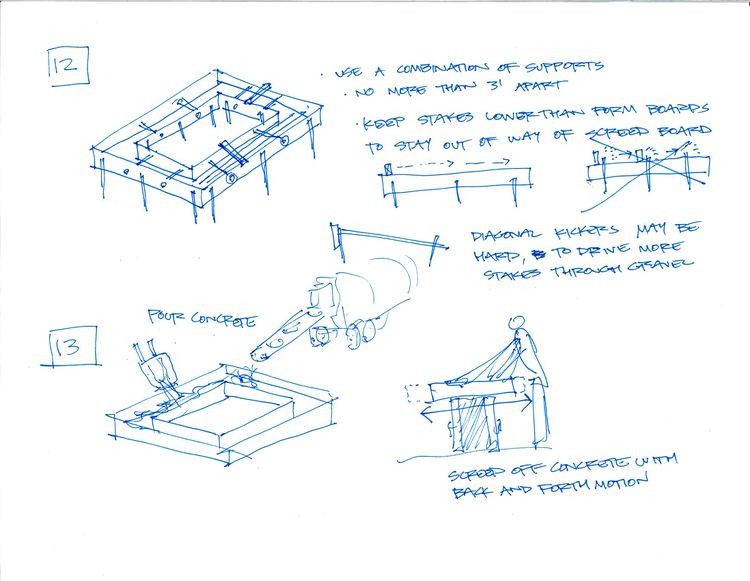
For allthread, do 2 at corners and 2 in middel - 4 per side. For blowout, do 2 of them per side - 1/3 way each. Rebar ends up at bottom 1/3 of boundation. Allthread about 5 inches down from top.
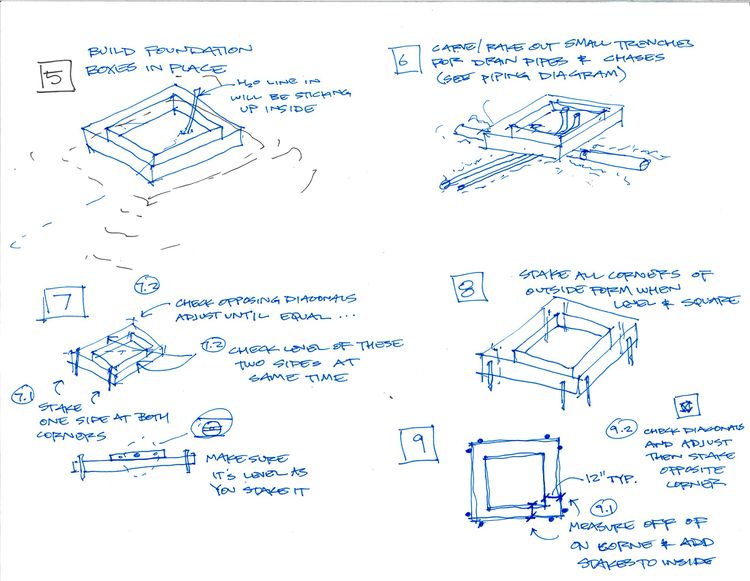
Stub out 8-12" of rebar.
Do 4 pieces of allthred per side -
Build Documentation
Assembling the MicroHouse foundation forms:
Pouring the concrete for the MicroHouse foundation:
Installed the drain pipes, the water inlet and the chase to enable thermal hydronics to connect to a future module.
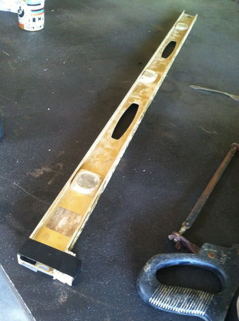
In order to facilitate measuring the fall on drain pipes at 1/4" per 1', a small 1" jig is taped to the end of a 4' level.
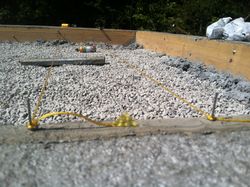
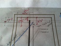
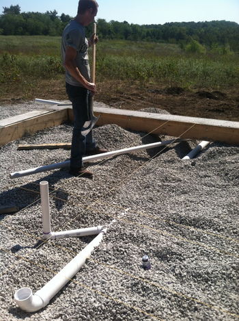
Strings were attached to the foundation form boards; intersections show where pipes come through floor. Final dimensions shown on marked up sheet to make any adjustments needed to utility module.
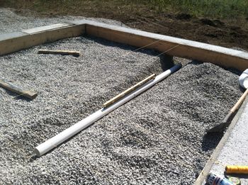
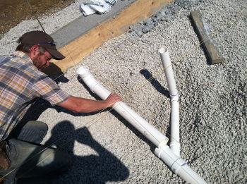
3" blackwater pipe was installed first. Gravel was dug out, pipe was put in place and checked for proper fall. "Shit runs downhill," the old plumber's golden rule says, but it runs downhill best if it sloped at 1/4" per 1'. Too much fall, and liquids can outrun solids.
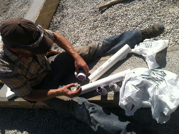
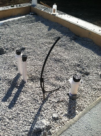
Always prime pipe before gluing to ensure a good bond. The vent pipe for the blackwater outlet (not shown in original drawing) penetrates the floor to come into the utility module. String intersections were used as guides and pieces were held in place to determine pipe lengths for cutting.
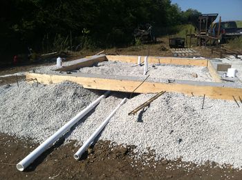
Once the 3" pipe was in place, a similar trench was dug out for the 2" line using the string as a guide. Here, the 2" and 3" lines are shown exiting the building. Both were kept low enough that the 6" line can go above them.
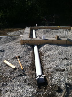
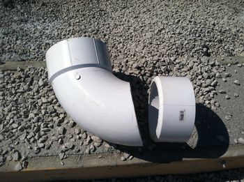
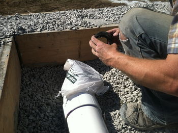
The last pipe to go in was the 6" chase that will eventually contain insulated PEX pipes to carry thermal energy to a future module. The 90 was too tall, so one of the bell-ends was cut off of it. Once the pipes were installed, the ends were capped with plastic bags and duct tape to avoid debris getting inside them before use.
The end result... pipe stubs right where we want them to be!

