UELVE MBC: Difference between revisions
m (→Design Concept) |
(→TODO) |
||
| Line 81: | Line 81: | ||
=TODO= | =TODO= | ||
* Simulation (playable game) using ODE (Open Dynamic Engine) which will be cool and also test real-world joint strength and drivability. See Hackrod. | * Simulation (playable game) using ODE (Open Dynamic Engine) which will be cool and also test real-world joint strength and drivability. See Hackrod. https://youtu.be/v__qoJsAs48 | ||
=Notes from Julia log= | =Notes from Julia log= | ||
Revision as of 18:54, 11 January 2020
The Embassy Elf (MBC UELVE)
The MBC (Myth Buster Car) is intended as a lightweight proof of concept for further development of additional larger (and smaller) 3 and 4 wheeled hybrid and tribrid electric vehicles such as solar vehicles, hydrogen-intake-injected and more. It's also intended to be eco-conscious, ultra-efficient, ludicrously high acceleration, low cost and eye-catching (hence the cross between a 2-seat sports car and a "Mad Max" off-road look), and intended for the average person to 3D print (or buy a pre-printed kit) and assemble in under five days.
Once completed the tools (including a specialist dedicated kevlar-crosshatching Fibre_Reinforced_Pipe_3D_Printer) and design techniques will be in place to expand the concept to other vehicles. These will not have the same "wow" factor however by going initially for a vehicle that is likely to be stressed to its limit (off-road, racing), design and materials flaws will be quickly found and fixed, long before more those other "mundane" vehicles begin production.
Acronym decoding:
- UELVEs: Ultra-Efficient Libre Vehicles for Everyone.
- MBC: the Embassy, or the "MythBusters Car" (get it?), in honour of their discovery that a golf-ball texture on a car bodypanels significantly improves fuel economy. https://www.youtube.com/watch?v=VUiGhyHC-1A
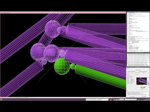
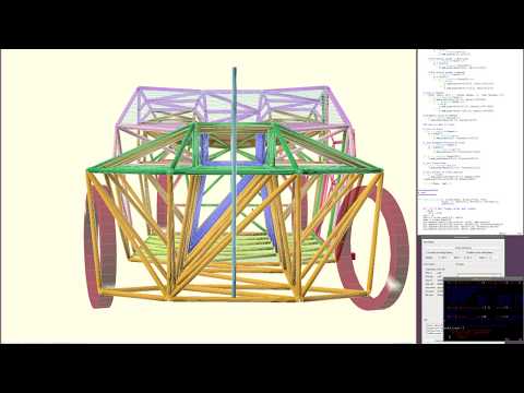
Frame Concept

Blue pipes are 1m measure sticks. Note that the body takes whatever form we would like.
Specifications
![]() Hint: Holy shit.
Hint: Holy shit.
- 4 wheels using mountain bike 19in rims and 2.75/19 motorcycle tires (26in outer diameter)
- 100kg weight (full, complete vehicle)
- 2 occupants
- Twin 3-5kW Axial Flux BLDC chain-driven motors (no gearbox needed)
- 1.1 x 1.5 x 3.4 metre dimensions with an "airbox" down the centre
- Only a 1.1 m^2 front surface area (due to the "air tunnel")
- 0-60mph in under four seconds (Sur-Ron "3" kW Motors can be pushed to 13kW for short durations, and there's two of them)
- over 200mpg at 55mph due to low weight, low rolling resistance, reduced surface area and low drag coefficient.
- capable of driving up a 50% gradient at around 25mph with 2 occupants.
Notes
- While world records are held for under 3 seconds, under 4 seconds is close to world records. [1]. We can emphasize here that for "acceleration per horsepower", ours here is probably a world record. Luke - have you done the numbers on this one?
- with the simulator i wrote a few years ago, yes. link at bottom of page. it's the reduced weight, reduced drag coefficient and the SurRon axial flux motors which can do 13KW for short bursts that do it. the world record is an MIT team EV with 4 hub motors. 0 to 60 in 1.9 seconds. in the slo mo the walls of the tires actually buckle under the acceleration.
Correction: that MIT team has been beaten by AMZ, who officially managed 0 to 60 (100km/h) in 1.513 seconds
http://img.youtube.com/vi/n2XiCYA3C9s/default.jpg
Design Concept
- Use high-end downhill mountain-bike parts that have been proven to be light, strong and effective up to a 50kg weight with an 80kg load, thanks to the Sur-Ron Electric Bike.
- Use twin Sur-Ron direct-drive 3-5kW Axial Flux electric motors
- Use twin ASI BAC4000 BLDC Controllers (or VESC Vedder BLDC Controllers http://vedder.se/2015/01/vesc-open-source-esc/)
- Outer skin using the GABoats technique (Geodesic Aerolite Boats) - http://gaboats.com
- Inner frame using 3D-printed fibre-reinforced "nodes" connecting continuous-fibre-reinforced pipes on a Fibre_Reinforced_Pipe_3D_Printer or getting carbon-fibre, hemp-reinforced tubes (or even Bamboo), based on the Divergent 3D "Blade" car manufacturing concept https://www.youtube.com/watch?v=vPv7PwS50OE
- Epoxy-soaked cloth "wrapping" carried out on joints, if necessary, using the Calfee Design Bamboo bike technique. https://calfeedesign.com/what-is-in-calfee-diy-kits/
- Swappable Modular batteries using the Open_Source_Battery_Pack
Source Code
- git clone http://lkcl.net/vehicle_3d/.git
BOM
estimated, todo steering and suspension, estimated total under USD 4000 excluding tools and batteries.
- 3D printed 15mm x 2mm kevlar/hemp continuous reinforced pipes (250 metres)
- 3D printed "nodes" (120)
- Kevlar twine (see gaboats)
- Dacron (see gaboats)
- QTY 2 Shimano Saint M820 mountain bike hydraulic brake sets (2 front, 2 rear)
- QTY 4 19in diameter downhill mountain bike wheels
- QTY 4 2.75/19in Shinko "Goldenboy" tires
- QTY 4 Fox DHX2 rear suspension sets with orange spring
- QTY 2 Sur-Ron 3kW BLDC Axial Flux Motors
- QTY 2 Sur-Ron rear swingarm (or structurally strong 3D printed equivalent, TBD)
- QTY 2 20kW 3 phase BLDC Motor Controllers (Vedder VESC)
- 6 guage wire (appx 5 metres)
- QTY 15 (appx) Open Source Battery Packs per kWh
- Bus Bars connecting packs together
- Bearings (lots)
Materials
- Contacted Olsson Ruby because ordinary nozzles are not going to cut it.
- kevlar: http://gaboats.com/products/
- CFF kevlar plastic https://markforged.com/product/kevlar-cff-spools/
- NylonX https://www.matterhackers.com/articles/create-custom-end-use-3d-printed-bike-parts-with-nylonx
TODO
- Simulation (playable game) using ODE (Open Dynamic Engine) which will be cool and also test real-world joint strength and drivability. See Hackrod. https://youtu.be/v__qoJsAs48
Notes from Julia log
https://wiki.opensourceecology.org/wiki/ImplicitCAD#Julia
recycling fibre reinforced plastic, fibres get shorter and shorter. (solution: add more back in?)
carbon fibre eco hostile (not going to use carbon fibre, use hemp fibre or wood fibre, see Da Ai Technology in taiwan)
use detroit technique: 3 pieces, front middle and back. matches with what i suggested, given that big printer is aiming for 4x4x8 ft. roof and floor will probably need to be separate in this design (so, 4 pieces)
Material Strength Test
the logical reasoning behind this test is to find out if, with fibre-reinforced plastic, the layer adhesion affects strength of the part under load when bolts are screwed directly into it.
- two M10 1.5mm pitch bolts (or close: 3/8 with 1/16in pitch)
- a 30 x 30 x 30mm cube made of fibre reinforced plastic with a smooth cylinder hole down the middle about 7 or 7.5mm diameter
- print that using 100% infill, fibre reinforced plastic, with a minimum 0.8mm nozzle, preferably 1.2mm, with the hole pointing UPRIGHT.
- screw the two M10 bolts in, using the thread to "tap" the holes, making them meet in the middle
- hang it from a bench by 1 bolt and keep putting weights on it until it breaks.
i need to know, how much weight it took. it might be a lot, before the cube breaks or the threads strip.
the next test is printing it where the hole is horizontal.
the "more advanced" version of that is for the hole to be at 45 degrees through the cube, i.e to test the effect of diagonal layers.
questions
- what kind of fibre plastic? answer: don't know enough to say. ideally several materials should be tested and the results fully documented.
- what diameter hole? assuming using the bolt as self-tapping, an M10 bolt with 1.5mm pitch has around a 1.5 mm inset, therefore 10mmm minus 1.5x2 equals 7mm, so between 7 and 7.5mm seems sensible to try. bottom line: if it cracks on insertion, the hole was too small!
- how should the weights be hung? doesn't matter as long as side-twisting is avoided (we are not testing shearing or twisting, here, yet, just pulling). strong rope tied or clamped to both bolts, one end fixed to a table, the other has weights attached, it doesn't matter. doesn't have to be sophisticated, here.
Expected Issues
One key issue to watch out for is the block cracking as the M10 bolt is screwed in. Normally, a tap/die would be considered, here.
The problem is that when using 1.2mm nozzles, it is extremely unlikely to be able to 3D print a matching 1.5mm thread for the bolt to fit in, therefore tapping the hole is the next option, and seeing if the bolt itself will achieve that is logical to attempt.
One alternative ie to look for very coarse threaded M10 bolts, or even trapeoizoidal bar, or, if this really doesn't work, some alternative lock mechanism, or a much larger diameter hole and use epoxy glue. of course, epoxy glue you are never going to be able to remove the bolt.

Videos
http://img.youtube.com/vi/myu6vBy0ASs/0.jpg
http://img.youtube.com/vi/9KKYw2uyQFQ/0.jpg
http://img.youtube.com/vi/kxjoSk2xUzA/0.jpg
Screenshots / Images

See Also
- Two Wheeled Velomobile
- Velomobile
- Summer_of_Extreme_Design-Build_and_Startup_Camp_Overview_of_Learning_Program
Useful Links
- Simple Vehicle Simulator including gears, gear-changes, wind-resistance, rolling-resistance, gradients etc. http://lkcl.net/ev/vehicle_simulator/output/Simulator.html