PowerCubeWiki: Difference between revisions
No edit summary |
|||
| Line 196: | Line 196: | ||
*Rebar 27" ½" 2 | *Rebar 27" ½" 2 | ||
= Jig (optional) = | == Jig Assembly (optional) == | ||
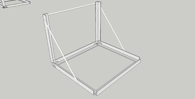
[[Image:JigSketchup.jpg|400px]] | [[Image:JigSketchup.jpg|400px]] | ||
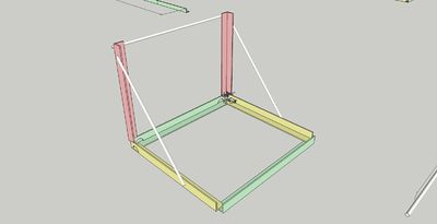
[[Image:JigCubeSketchup.jpg|400px]] | [[Image:JigCubeSketchup.jpg|400px]] | ||
The jig is an optional piece of fabrication equipment that can be very useful to have should you be creating several power cubes concurrently. The materials for the cube are assembled in the jig in half sections and tacked and welded in place. | The jig is an optional piece of fabrication equipment that can be very useful to have should you be creating several power cubes concurrently. The materials for the cube are assembled in the jig in half sections and tacked and welded in place. | ||
Revision as of 20:48, 24 August 2011
| Power Cube | ||
|---|---|---|
| Home | Research & Development | Bill of Materials | Manufacturing Instructions | User's Manual | User Reviews | 
| |
Overview
See Power_Cube_Fabrication_Procedure for initial steps.
Work in progress by Tom Griffing, August 13, 2011: File:Powercube.odt
Power Cube
Port from ODT
Power Cube Version 4
Contents
Table of Contents
Power Cube 1
Contents 2
Introduction 3
Bill Of Materials 4
Discrete parts 4
Steel 5
Subassembly Fabrication 6
Assembly 8
User Guide 15
Introduction
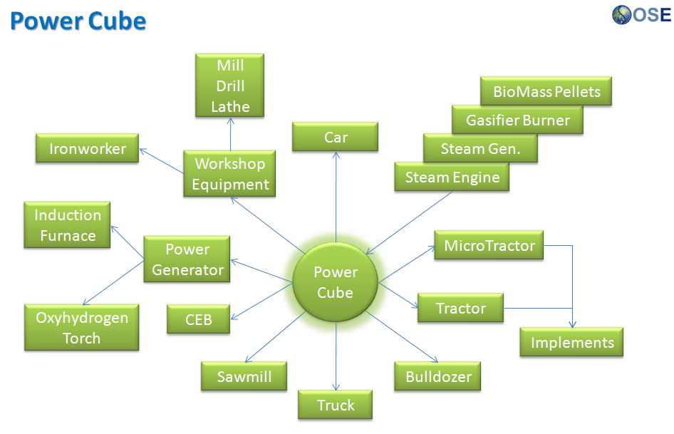
The Power Cube is an universal, self-contained power unit that consists of an engine coupled to a hydraulic pump for providing power in the form of hydraulic fluid at high pressure. It connects via quick couplers and quick-connect hydraulic hoses to devices such as:
LifeTrac ◦ <image> Microtrac ◦ <image> Bulldozer ◦ <image> Open Source Car (OSCar) ◦ <image>
This document provides information for building and using a Power Cube as part of the Open Source Ecology (OSE) project.
Bill Of Materials
Discrete parts Name Qty Dimensions Manufacturer / Retailer Part No. Engine 1 Brigs & Stratton 27 HP Lovejoy Coupler 1 2.5" x 2.25" Hydraulic Pump 1 12.11 GPM Prince SP20B16 Hydraulic Filter & Head 1 3.5” x 5” Zinga AE-10 14 GPM Hydraulic Tank Strainer 1 1 1/2" NPTM to 1" NPTF SurplusCenter.com 9-7290-100 Adapter 1 1” x ¾” SurplusCenter.com 9-5405-12-16 90 degree elbow, male to male 3 ¾” SurplusCenter.com 9-5500-12-12 Hydraulic Quick-coupler Male 1 ¾” Safeway S71-4 Hydraulic Quick-coupler Female 1 ¾” Safeway S45-2 Hydraulic Quick-coupler Female 1 3/8” SurplusCenter.com 9-7381 NPT Weld-In Tank Flange 1 1 1/2” NTPF SurplusCenter.com 9-7843-24 NPT Weld-In Tank Flange 1 3/4” SurplusCenter.com 9-7843-12 Hose barb 1 ¼" NPTM x 3/8" SurplusCenter.com 455-BB 90 degree hose barb 1 1” NPTM x 1” SurplusCenter.com 9-4501-16-16 Hydraulic Suction Hose 30” 1” SurplusCenter.com 9-1279 Hydraulic Oil Cooler 1 14” x 14 ½” SurplusCenter.com 9-9232 Hydraulic Hose 1 1/2” x 12” SurplusCenter.com 905-1212 12 Volt radiator fan 1 12” - 14” Auto Part Rubber Fuel Line 1 24” Auto Part Battery 1 5" x 7.5" x 7.5" Walmart UIP-7 Hydraulic Mount 2 4.75" x 3" Galvanized Nipple 4 1” Home Depot 64310 Galvanized Elbow 2 1” Home Depot 510-003HN Galvanized Washer 4 2 ½” ?? ?? Galvanized Round 2 2” ?? ?? Teflon Tape 1 roll ½” wide Home Depot ?? 1 Gauge Wire 30” 1 gauge Auto Part ?? 1 gauge ring connector - or - Copper tubing 6 - or - 9” 1 gauge - or - 3/8” Auto Part ?? Ignition Switch 1 12 V Fan Switch 1 Bolt (Angle iron attach) 4 ½” x 2” x 12 TPI Nut (Angle iron attach) ½” x 12 TPI Washer flat 8 ½” Bolt (Engine mount) 4 ¼” x 2” 16 TPI Nut (Engine mount) 4 ¼” x 16 TPI Bolt (Hydraulic motor mount) 4 ¾” x 4” x 12 TPI Nut (Hydraulic motor mount) 8 ¾” 12 TPI Lock washer (Hydraulic motor mount) 4 ¾” Nut (Oil cooler) 4 Bolt (Oil cooler) 4 Bolt (Solenoid mount) 2
Steel Type Width Thickness Total Length (rounded up) Angle 2" ¼" 370" (Frame, support) Angle 2” 1/8” 6” (Key switches, choke) Plate 8" ¼" 38" (Engine mount, gas tank) Plate 2” ¼” 98” (Oil cooler mount, Battery mount) Plate 6" ¼" 24" (Hydraulic reservoir) Plate 4” 3/8” 54” (Quick attach) Tube 4” x 8” ¼” 14 ½” (gas tank) Tube 6” x 12” ¼” 27 ½” (Hydraulic reservoir) Tube 2.5” dia 1/8” 2” (section strainer extension) Tube 1 9/16” 1/8” 12” (Galvanized Muffler Pipe) Tube 6 cm 1/8” 14” (Galvanized Muffler Pipe) Plate 8” 3/16” 3” (Galvanized muffler mount)
Subassembly Fabrication
Many of the items listed in the Bill Of Materials require preparation before use in assembly of the Power Cube. This includes drilling and cutting steel up to 3/8” in thickness. These are the parts for assembling a Power Cube.
- 1. Engine mounts
- a) ¼” x 8” x 12” Plate
- b) ¼” x 8” x 9” Plate
- <image>
- c) ¼” x 2” x 2” x 8” Angle
- d) ¼” x 2” x 2” x 29” Angle
- <image>
- 2. Hydraulic pump mount
- a) ¼” x 8” x 8” Plate
- <image>
- 3. Quick attach mounts
- a) [2] 3/8” x 4” x 27” Plates
- <image>
- 4. Fuel tank
- a) [2] ¼” x 4” x 8” Plates
- <image>
- b) ¼” x 2” x 24” Plate
- <image>
- c) 4” x 8” x 14 ½” Tube
- <image>
- 8 5. Oil Cooler Mount
- a) [2] ¼” x 2” x 24” Plates
- b) [2] ¼” x 2” x 22” Plates
- c) [2] ¼” x 2” x 1” Plates
- <image>
- 6. Key Switches and Choke
- a) [3] 1/8” x 2” x 2” x 2” Angle
- <image>
- 7. Electrical cables
- Note: The connectors can be purchased from an auto parts store – be aware that they usually require a crimper to attach to the cables. Alternatively, 3/8” copper tubing can be used in 1 ½” long pieces instead. Strip 1 ½” insulation from the cable, fully insert fully into 1 ½” copper tube, flatten end with a hammer and drill hole.
- a) [2] 11” 1 gauge
- b) 8 ½” 1 gauge
- 8. Battery Mount
- a) [2] ¼” x 2” x 2” x 4 3/4” Angle
- b) [2] ¼” x 2” x 5/8” Plate
- <image>
- 9. Hydraulic reservoir
- a) [2] ¼” x 6” x 12”
- b) 6” x 12” x 27 ½” Tube
- c) 2” x 2 ¼” x 1/8” Tube
- <image>
Assembly
Power Cube assembly requires all the parts listed in the Bill Of Materials to be available and prepared as detailed in the “Fabrication” section (above). Assembly requires a welder (electric or torch) capable of welding metal 3/8” thick.
Optional: Jig for frame assembly
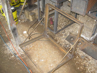
The welding “jig” in the image below is helpful to insure square angles while assembling the Power Cube. Materials List ¼” x 2” x 2” Angle Iron: 14' ½" Rebar: 7' 2”
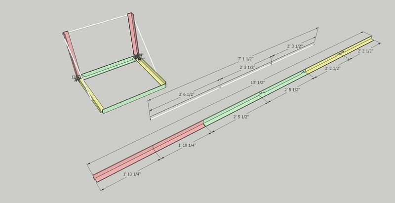
Cut List Type Length Dimensions Quantity Color
- Angle 22" ¼” x 2 x 2" 2 (red)
- Angle 26" ¼” x 2” x 2” 2 (yellow)
- Angle 29" ¼” x 2" x 2 2 (green)
- Rebar 30.5" ½" 1
- Rebar 27" ½" 2
Jig Assembly (optional)
The jig is an optional piece of fabrication equipment that can be very useful to have should you be creating several power cubes concurrently. The materials for the cube are assembled in the jig in half sections and tacked and welded in place.
Materials List
Total Length 14' Angle (2"x1/4") 7'2" Rebar (1/2")
Cut List
| Type | Length | Dimensions | Quantity | Color |
| Angle | 22" | (2"x1/4") | 2 | (red) |
| Angle | 26" | (2"x1/4") | 2 | (yellow) |
| Angle | 29" | (2"x1/4") | 2 | (green) |
| Rebar | 30.5" | (1/2") | 1 | |
| Rebar | 27" | (1/2") | 2 |
Assembly of the Jig is fairly straight forward. Tack and weld the pieces in place.
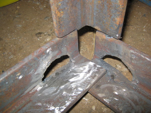
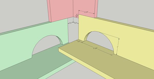
Be sure to note the overlapping order and the notch made at the bottom of the 1'10 1/4" piece (red). Torch holes in the corners below the frame as seen above. This allows room for the welding torch to get to the PowerCube while welding.
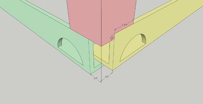
Also note that the corners are offset 3/4" (1/2" measured on the interior), to give room for the cube to sit snugly in the frame (and a convenient gap for welding the corners.)
Tack weld the two shorter rebar sections at roughly a 45 degree angle on the sides. Add a long rebar section to span the gap. Precision is not as important with these, they are more there for stability.
With any luck, you'll have your jig, ready to crank out Power Cubes with!
Frame
- a) Top / Bottom Rectangles
Position two ¼” x 2” x 2” x 29” pieces angle iron on top of two 27” angle pieces as shown below. Check that all joints are square, then tack and weld joints.
- b) With one welded rectangle on the bottom, position the 24” pieces outside corner joints as shown below. Check that the angles are square, then tack and weld.
- c) Position the second rectangle as shown below, then tack and weld. Inspect all corners to verify secure welds.
- 3. Gas tank
All welds assembling the tank must be quality welds, as they must not leak. Be careful not to “over weld” the tank to the mount.
- a) Clean the inside of the ¼” x 4” x 8” tube and the two ¼” x 4” x 8” plates – anything left on these surfaces will end up in the gasoline and could clog the engine when started. Tack and weld the plates on each end of the tube, taking care to orient the top plate with the filler hole as shown in the diagram below.
- <image>
- b) Weld the ¾” tank flange to the smaller hole.
- <image>
- c) Perform a “soap bubble” test on the tank. Securely cover the larger hole (use something like strong tape), pressurize the tank using the smaller hole and cover the tank surface with soapy water. Look closely for new bubbles, mark any leaks and re-weld securely. Repeat soap bubble test if re-welded.
- d) Tack and weld the gas tank mount (¼” x 2” x 24” plate) to the frame.
- e) Tack and weld the gas tank to the gas tank mount as shown below.
- 4. Hydraulic tank
All welds assembling the tank must be quality welds, as they must not leak. Be careful not to “over weld” the tank to the mount.
- a) Clean the inside of the tubes and the two end plates – anything on these surfaces will end up in the hydraulic oil and could damage the pump or cylinders.
- b) Tack and weld the 6” x 12” plates to both ends of the 6” x 12” tube. Pay attention to the orientation of the plate with the filler hole – see the diagram below.
- c) Tack and weld the strainer extension tube to the tank, centered around the strainer hole.
- d) Insert the strainer into the tank flange and insert it into the strainer extension tube – verify that it slides in without binding or bottoming and that the flange is flush with the end of the tube. Remove the strainer from the flange and tack and weld the tank flange.
CAUTION: Keep the strainer away from the welding, as its thin wires are easily burned.
- e) Perform a “soap bubble” test on the tank by securely covering the larger hole (use something like strong tape), pressurizing the tank using the smaller hole and cover the tank surface with soapy water. Mark any leaks and re-weld securely. Repeat soap bubble test if re-welded.
- f) Weld it to the frame as shown with 4 1” welds. The tank is ¼” and it can be easily damaged by over-welding. Spacers may be needed on the sides near the top to keep everything snug.
- 5. Engine Mounts and Hydraulic Motor Mount
- a) Position the ¼” x 2” x 2” x 29” angle 12 ½” from the hydraulic tank (see diagram below). Tack and weld it to the frame.
<image>
- b) Place the ¼” x 8” x 8” plate on the angle iron and secure with two bolts.
- c) Place the ¼” x 2” x 2” x 8” angle on top of the ¼” x 8” x 12” plate, align the bolt holes and secure with two bolts. Align this assembly with the ¼” x 8” x 8” plate in the prior step and position the angle against the hydraulic tank, 3” below the tank top as in the diagram below, then tack and weld to tank.*<image>
- d) Tack and weld the corner formed by the two 8” plates.
- e) Examine the engine shaft – it should be 3” long. If longer, cut the shaft to 3” long.
- f) Place the engine on its mounting plate and verify that the shaft extends through the hole.
- g)
- 6. Battery mount
- a) Weld the ¼” x 2” x 5/8” plates to the ends of the ¼” x 2” x 2” x 4 3/4” plates as shown below.
- <image>
- b) Weld the two mounts to the angle iron and tank to form a rectangle for the battery as shown below.*<image>
- c) After the mount has cooled, lower the battery into the rectangle to verify it fits properly.
- 7. Oil cooler and fan mounts
- a) Position the two ¼” x 2” x 22” plates to the outside of the frame, adjust so the oil cooler mounting bolts match the holes in the plates and is positioned as in the diagram below. Tack and weld the mounts in to the frame. Verify that the oil cooler bolts match the holes in the mounts.
<image>
- b) Use the mounting holes in the fan shroud and the oil cooler width for positioning the mounting plates as shown in the diagram below. Position the four ¼” x 2” x 1” plates, then tack and weld. Position the two ¼” x 2” x 24” plates against the 1” plates, then tack and weld. Place the fan on the supports and mark the mounts with bolt hole positions. Place the bolt heads against the fan mounting plate and weld in place. Verify that the bolts match the holes in the fan. Inside the frame, adjust the fan position to to position fan shroud ¼” from oil cooler fins. Be careful with radiator as the delicate fins are easily bent and damaged.*<image>
- 8.
- Mount the hydraulic fittings, hydraulic motor, gas tank, battery and wires. Finish it up to complete your very own OSE Powercube 4.0!
- User Guide
- This section is intended for the end user of the Power Cube.
*1.	Caution
*a)	Weight
*b)	Hydraulic hazards
*c)	Ventilation
*2.	Mounting
*a)	Quick attach connector
*3.	Initial startup and testing
*a)	Initial Setup
- Gasoline
- Hydraulic Fluid
- Battery Connection
- b) Startup
- c) Hydraulic Test
- 4. Routine use
- 5. Maintenance
- a) Check fluids
- b) ? ? ?
- 6. Troubleshooting
- a) Engine won't start
- b) Loud noise
- c) No hydraulic power
