Hydraulic Connection Diagram Standards: Difference between revisions
Jump to navigation
Jump to search
No edit summary |
No edit summary |
||
| Line 1: | Line 1: | ||
To draw a hydraulic diagram: | To draw a hydraulic diagram: | ||
#use a vector graphics program such as [[Inkscape]] or a cut and paste program Google Drawings | #use a vector graphics program such as [[Inkscape]] or a cut and paste program like Google Drawings | ||
#paste in component images | #paste in component images | ||
#link connections via lines | #link connections via lines | ||
Revision as of 18:06, 29 August 2012
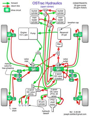
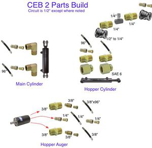
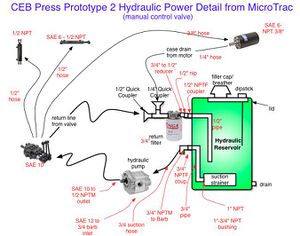
To draw a hydraulic diagram:
- use a vector graphics program such as Inkscape or a cut and paste program like Google Drawings
- paste in component images
- link connections via lines
- use simple drawings to elucidate context
- label the specifications of hydraulic components and fittings
- use OSE Title Block


