Industrial Robot/Manufacturing Instructions
Jump to navigation
Jump to search
| Industrial Robot | ||
|---|---|---|
| Home | Research & Development | Bill of Materials | Manufacturing Instructions | User's Manual | User Reviews | 
| |
Tooling and Infrastructure
Measuring and Marking
- Scriber
- Metal Rule
- Combination Set
- Center Punch
Taps and Dies
- 1/2" - 13 Taps
- 9/16" - 18 Taps
- Tap Wrench
Port Cutting
- SAE6 Port Contour Cutter
Drilling
- Cordless Drill
Twist Drill Bits
- 1/2"
- 3/8"
- 1/4"
- 5/32"
- 1/8"
Soldering
- Soldering Iron and Stand
- Solder
Torching
- Oxy-acetylene Torch
Turning
- Lathe
- Cutting tools - turning, grooving
Hand Tools
- Adjustable pliers
- File
Fabrication
Foundation
- The foundation can be a large tube that is flanged at both ends; one flange is fastened to the ground while the other is fastened to the axis 1 slewing bearing.
- Alternatively, the foundation can be a plate that is fastened at its corners to the ground. On top of this ground-mounted plate, 4 upright pillars are welded or fastened; then, another plate is fastened upon these pillars then fastened again to the axis 1 slewing bearing.
- Alternatively, the foundation can be two long square tubes that are fastened to the ground parallel and at a sizeable distance from each other. Then two more square tubes, parallel to each other but perpendicular to the first two tubes, are fastened on top of the first two tubes. Upright square bars are fastened to the intersections of the first and second tubes, making that 4 bars in total, being 1 to each intersection. A plate is fastened on top of these bars then fastened again to the axis 1 slewing bearing.
Base
- The base can be comprised of an angle that partially fastens to the axis 1 slewing bearing and axis 2 slewing bearing. This angle also would allow mounting of the axis 1 hydraulic motor and axis 2 hydraulic motor, as well as the axis 1 encoder and the axis 2 encoder.
- Alternatively, the base can be comprised of a plate that completely fastens to the axis 1 slewing bearing and another plate that completely fastens to the axis 2 slewing bearing. Then an angle fastens to the aforementioned 2 plates; this angle also would allow mounting of the axis 1 hydraulic motor and axis 2 hydraulic motor, as well as the axis 1 encoder and the axis 2 encoder.
Base-to-Mid
- The base-to-mid can be comprised of a large bar that is partially fastened to the axis 2 slewing bearing and axis 3 slewing bearing.
- Alternatively, the base-to-mid can be a plate that is completely fastened to the axis 2 slewing bearing and another plate that is completely fastened to the axis 3 slewing bearing. Then, these two plates would be fastened to the ends of a large bar.
Mid
Mid-to-End
End
End-Effector
Stepper Mount
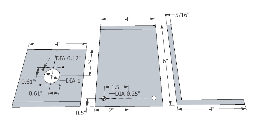
[6] Stepper Motor Mount Angle
- Mark cuts with scriber and try-square
- Cut with torch cutter
- Mark holes with scriber, rule, try-square, and center punch
- Drill holes with 1" bit, 1/4" bit, 1/8" bit, and cordless drill
Media:StepperMotorMountAngle.jpg
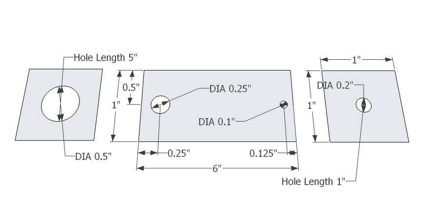
[6] Stepper Motor Mount Plate
- Mark cuts with scriber and try-square
- Cut with torch cutter
- Mark holes with scriber, rule, try-square, and center punch
- Drill holes with 1/4" bit and cordless drill
Media:StepperMotorMountPlate.jpg
[6] Shaft Coupling
- Mark cuts with scriber and box-square
- Cut with torch cutter
- Mark thru hole with scriber, combination set, and center punch
- Drill holes with 1/2" bit, 1/4" bit, 5/32" bit, and cordless drill
- Tap holes with 10-24 taper/intermediate/plug taps and tap wrench
Assembly
Assemble Stepper Motor Mount
- As shown below, repeat for a total of 6 mounts
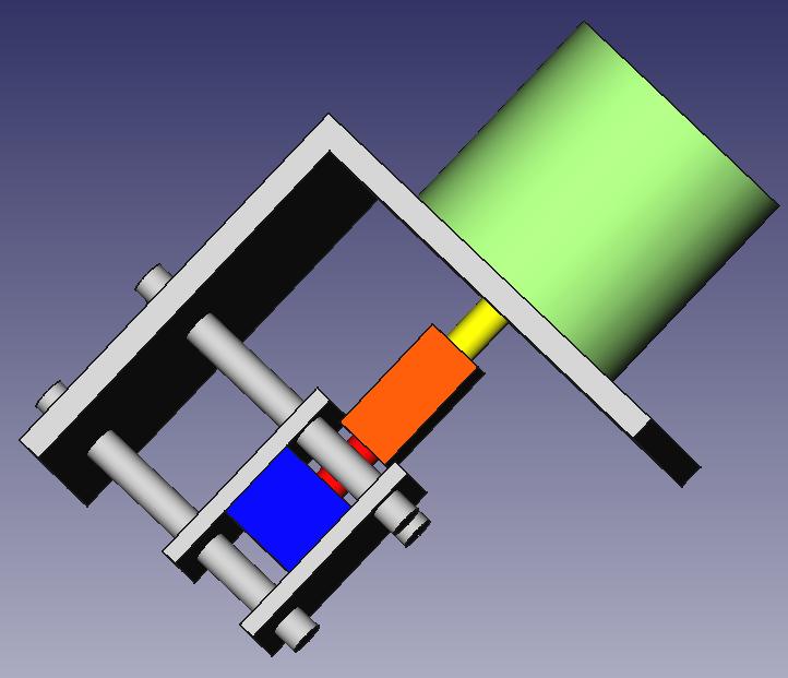
- Solder PWM driver Instructions