Jonathan Kocurek Log
Permanent Links
LifeTrac 6 Production Requirements
LifeTrac 6 Product Development Board
Master Product Development Board
Product Concept & Key Performance Parameters Template
DPV Orientation and Message Board
Collaborators' Logs
Tues Aug 13, 2013
Marcin came in today and we talked about what Design Requirements are needed for the Loader Arm. I've been trying to draw up a way to document these design requirements for each module included in the LifeTrac. So far, I've just been creating Google Drawings of the module design requirements. I provided a link to edit the drawing and a visual representation of it to the LifeTrac 6 Modules page. That way whenever the drawing is updated, the visual representation should also update on the wiki.
I discovered that sometimes the visual representation doesn't always update in real time. If that happens, it's because your internet browser's cache has to be deleted.
Mon Aug 12, 2013
We had a meeting with Marcin and Katie today about work progress. For the past week, the tractor design team has been making changes on the various modules that comprise LifeTrac 6. Several team members are new arrivals (including myself) and have trouble tracking down the knowledge required to make educated decisions on how to proceed on the LifeTrac. Traction for newcomers requires 3 important things:
- A set of operational definitions
- Design Requirements
- A centralized repository of relevant information from past workers
I have set out in an effort to fill in some of the gaps in these elements.
Important Orientation Elements for Newcomer Designers
Operational Definitions - First is to create a universal nomenclature for the hardware pieces we are working with.
Design Requirements - Marcin and the team worked together today to nail these down.
Design Repository - I created a LifeTrac 6 Modules Page where the most current screenshots and .skp files are located on the modules needed to build the tractor. Also it shows concept art and names of parts.
Sun Aug 11, 2013
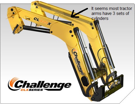
With only two sets of actuators, and the design rules I am aware of right now, this is the best configuration I've been able to draw up.
It seems that some tractor arms have 3 sets of actuators for a larger range of motion. Should we explore this?
PowerCube contents fit very nicely inside the 4x4 tubing config.
File:PowerCube Guts in 4x4.skp
Sat Aug 10, 2013
We made significant progress on the tractor loader design and interface with the cab. As of now, the bucket can dump at a 45 degree angle when the bucket tip is above 7' from the ground. I've tried many many configurations to try to follow the design constraints given us, namely that the bucket must dump at 60 degrees when the tip is @ 7' and have the bucket able to dig 1' below the ground when the bucket is flat and the arms are at rest. So far, I haven't figured out how to do all of those. The current version seems to be a possibility. If the bucket can clear the 7' CEB hopper height and dump down into it while lowering the arms I think this current version will work fine.
Fri Aug 9, 2013
Dave and I worked on getting the PowerCube Modules guts to fit into a 4x4" tube frame and attach it to the articulated steering pivot and the rear wheel base.
Thurs 8/8/2013
Wed 8/7/2013
I finished the 36” stroke hydraulic arm and drew up a new frame for the PowerCube. I used 36” 4x4” tubing for the outside cube frame, creating an open cube space interior of 28x28x28”. I also went down to the shop to inspect the existing PowerCube with the angle iron frame. The outer dimensions of the angle iron frame are ~30x30x30”. The interior guts do not fit exactly within 28x28x28, but with minor modifications on a new model, they can be made to fit.
Lucas briefed Dave, Scott and I on the to do tasks on updating the LifeTrac. We will be changing the loader arms, the PowerCube frame, the articulated steering pivot, the ground-hugger pivot, and the width of the wheelbase and cab.
Tues 8/6/2013
This morning Lucas had me work on drawing up a hydraulic arm in sketchup. I won’t lie, sketchup is definitely not as powerful of a program as I’m used to, but I’m learning it. The hydraulic arm model will be used as a measurement tool in the latest version of the LifeTrac Tractor.
The 3D printer we worked on last night needed to be re-calibrated again today. We used a more accurate measurement system - an indicator dial - to ensure the nozzle had flat printing plane on the printing board.
In the afternoon, Lucas had me do another hydraulic arm, this time at a 36” stroke.
Mon 8/5/2013
I came into Kansas City today by Greyhound Bus. Since my phone died on the way here, I was unable to confirm the time which I needed to be picked up. Luckily when I arrived, there was a way to charge my phone and contact Scott, who came to get me. After traveling back to Maysville, MO, I unloaded my things and took a tour of the facilities. The shop looks quite impressive. I met the other Dedicated Project Visitors: Jon, Dave, and Lucas.
Jon has been having trouble with the 3D printer that will be used in the design of the HydraFabber. The extruder nozzle would not line up properly with the building board and thus not be able to print. At first, we thought to level the board and test the nozzle by eyeballing it as we moved it left and right. After some time, we realized the real problem wasn’t the base board, it was the rails that supported the nozzle that were at an angle. After adjusting the Z-Axis threads to match each other, the process was simple to get it to print.
Sat Jun 1, 2013
Converted SGT01 Wikispeed car STEP files into Sketchup.


