Steam Engine Build/Piston Connector Rod
Jump to navigation
Jump to search
Main > Energy > Steam Engine
Description
The connector rod connects the piston stem to the crank on the crankshaft. One end is fixed to the piston stem and travels in a reciprocal, linear motion. The other end is attached to a crank on the crankshaft and travels in a circular motion. The crankshaft end contains a bearing case and ball bearings to reduce wear on the crankshaft.
The connector rod is built up from three elements:
- Coupler
- Bearing Case
- Rod
Drawing
Instructions
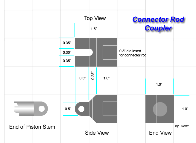
Coupler
Using a piece of high quality steel:
- Cut a 1.5" length from 1.0" square bar stock
- Drill a 0.5" dia hole in one end to a depth of 0.75"
- From the top face, drill a 0.25" hole at 0.5" from the left end.
- Cut a slot 0.25" wide to meet the hole just drilled.
- Bevel the piece at a 45 degree angle as shown
- Drill a 0.25" hole 0.25" from the end into the side face
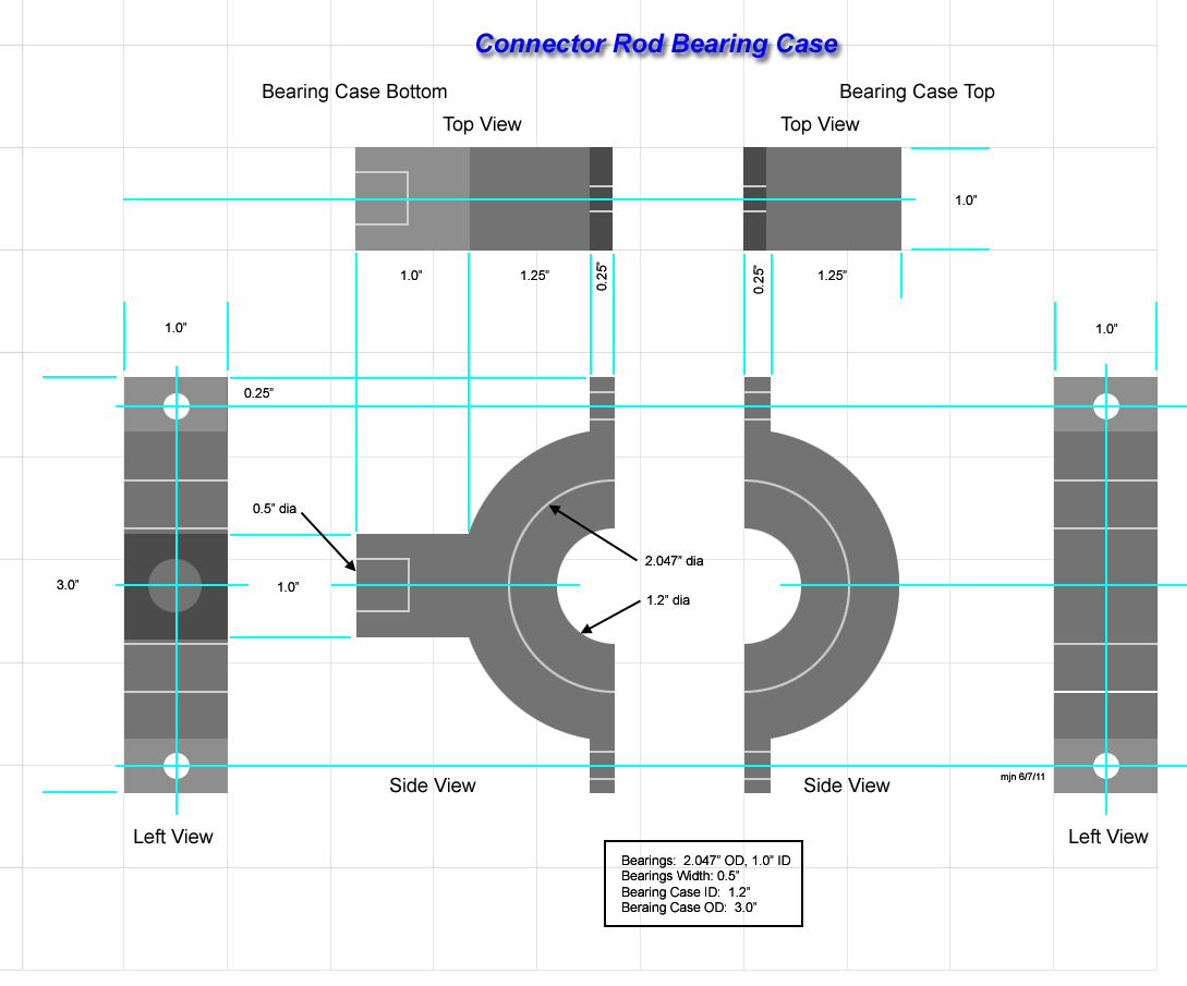
'Bearing Case
The bearing case can either be milled from high quality steel, or the circular portion turned on a lathe and bolt tabs welded on.
- Drill bolt holes 0.25" dia.
- Inside bore is 1.2" dia to hold a bearing unit with a 1.0" bore (shaft size)
- A cylindrical channel is cut inside 0.5" wide and 0.647" deep
Assembly
- Cut a length of 0.5" rod 8.0" long
- Insert the rod into the coupler and weld it
- Insert the rod into the bearing case and weld it.

