Industrial Robot/Manufacturing Instructions
| Industrial Robot | ||
|---|---|---|
| Home | Research & Development | Bill of Materials | Manufacturing Instructions | User's Manual | User Reviews | 
| |
Open Section Fabrication and Assembly

Structure
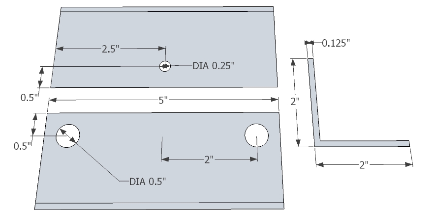
Foundation
- [2] Main tubes
- [2] Support tubes
- [4] Raising Bars
- Drill 3 holes in each bar (redone image TBD)
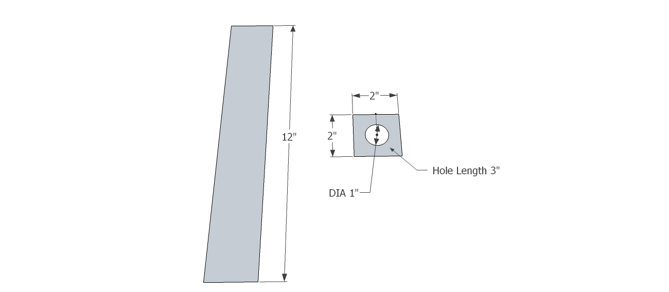
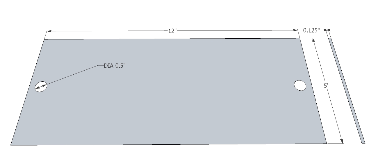
- [1] Plate
- Drill 13 holes (redone image)
Fasteners
- [12] Bar Bolts
- [4] Ground Bolts
- [4] Plate Bolts
Main Arm
- [1] Bar
- Drill 18 holes
- [8] Bolts
- [8] Bolts
Forearm
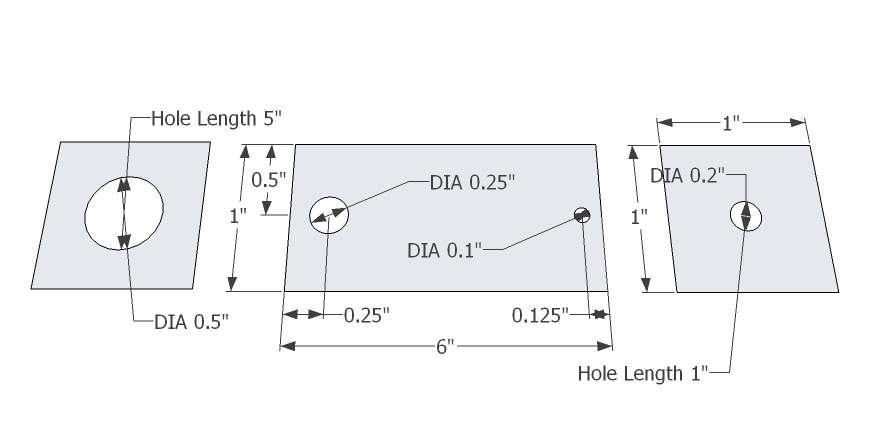
- Perpendicular Plate
- Drill 9 holes
- Weld to tube
- Tube
- Parallel Plate
- Drill 9 holes
- Weld to tube
- [8] Bolts
- [8] Bolts
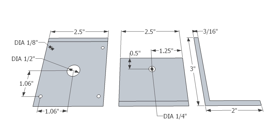
Gearbox 1,2
- [2] Hydraulic Motor
- [1] Angle
- Mark hole centers with a scriber, rule, nipple punch (for torch holes), and center punch (for drill holes)
- Mark torch holes with a divider
- Drill holes with 1/2" bit and cordless drill
- Torch holes with torch cutter
- Smooth with a file
- [2] Input Plate
- Note: Location of motor mounting holes TBD
- Mark hole centers with a scriber, rule, nipple punch (for torch holes), and center punch (for drill holes)
- Mark torch holes with a divider
- Drill holes with 1/2" bit and cordless drill
- Torch holes with torch cutter
- Smooth with a file
Media:IRGearbox12InputPlate.jpg
- [4] Side Plate
- Mark holes with scriber, rule, and center punch
- Drill holes with 1/2" bit and cordless drill
- Smooth with a file
Media:IRGearbox12SidePlate.jpg
- [2] Cover Plates
- Mark holes with scriber, rule, and center punch
- Drill holes with 1/2" bit and cordless drill
- Smooth with a file
Media:IRGearbox12CoverPlate.jpg
- [4] Outer Race Plate
- Mark drill holes with scriber, rule, and center punch
- Mark torch hole with scriber, rule, nipple punch, and divider
- Drill with 1/2" bit and cordless drill
- Torch with torch cutter
- Smooth with a file
Media:IRGearbox12OuterRacePlate.jpg
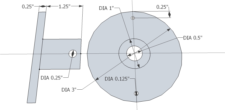
- [2] Round Bar
- Mark drill holes with scriber, combination set, and center punch
- Drill with 1/2" bit and cordless drill
- Tap with 1/2" - 13 taper/intermediate/plug taps and tap wrench
Media:IRGearbox12OutputShaft.jpg
- [4] Inner Race
- Mark hole with scriber, combination set, nipple punch, and divider
- Torch with torch cutter
- Turn with lathe
- Groove with lathe
- Smooth with file
Media:IRGearbox12InnerRace.jpg
- [2] Output Hub
- Mark hole with scriber, combination set, nipple punch, and divider
- Torch with torch cutter
- Turn with lathe
- Groove with lathe
- Smooth with file
Media:IRGearbox12OutputHub.jpg
- [2] Support Hub
- Mark hole with scriber, combination set, nipple punch, and divider
- Torch with torch cutter
- Turn with lathe
- Groove with lathe
- Smooth with file
Media:IRGearbox12SupportHub.jpg
- [1] Loose Ball Bearings
- [12] Side Plate Bolts
- [12] Side Plate Nuts
- [4] Cover Plate Bolts
- [4] Cover Plate Nuts
- [4] O-ring Seal
- [4] Output Shaft Bolts
- [4] Lube Bolts
- [2] Input Gear
- [2] Output Gear
- [2] Key
Gearbox 3,4
Forearm Angle
- As shown below
- As shown below
- Input Plate
Media:IRGearbox3456InputPlate.jpg
- Note: Location of mounting holes for hydraulic motor unknown
- Side Plate
Media:IRGearbox3456SidePlate.jpg
- Cover Plates
Media:IRGearbox3456CoverPlate.jpg
- Outer Race Plate
Media:IRGearbox3456OuterRacePlate.jpg
- Output Hub
Media:IRGearbox3456OutputHub.jpg
- Output Shaft
Media:IRGearbox3456OutputShaft.jpg
- Keyed
- Inner Race
Media:IRGearbox3456InnerRace.jpg
Gearbox 5,6
- Wrist Angle
- As shown below
- Input Plate
Media:IRGearbox3456InputPlate.jpg
- Note: Location of mounting holes for hydraulic motor unknown
- Side Plate
Media:IRGearbox3456SidePlate.jpg
- Cover Plates
Media:IRGearbox3456CoverPlate.jpg
- Outer Race Plate
Media:IRGearbox3456OuterRacePlate.jpg
- Output Hub
Media:IRGearbox3456OutputHub.jpg
- Output Shaft
Media:IRGearbox3456OutputShaft.jpg
- Keyed
- Inner Race
Media:IRGearbox3456InnerRace.jpg
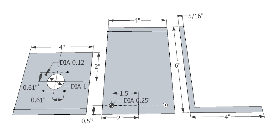
Encoder Mount
- Encoder Mount Support Angle
- Mark drill holes with scriber and rule
- Drill holes with 1/2" bit, 1/4" bit, and cordless drill
Media:IREncoderMountAngleA.jpg
- Encoder Mount Main Angle
- Mark drill holes with scriber and rule
- Drill holes with 1/4" bit, 0.15" bit, and cordless drill
Media:IREncoderMountAngleB.jpg
- Encoder Mount Coupling
- Turn with lathe and cutting tool
- Mark thru- and mount holes with scriber, combination set, and center punch
- Mark set hole with box square
- Drill holes with 1/2" bit, 1/4" bit, and cordless drill
Media:IREncoderMountCoupling.jpg
Stepper Mount
- Stepper Motor Mount Angle
- Mark holes with scriber, rule, and center punch
Media:StepperMotorMountAngle.jpg
- Stepper Motor Mount Plate
- Mark holes with scriber, rule, and center punch
Media:StepperMotorMountPlate.jpg
- Shaft Bar
- Mark thru hole with scriber, combination set, and center punch
Assemble Components
Assemble Gearboxes

Assemble Industrial Robot
- As shown below
Assemble Stepper Motor Mount
- As shown below, repeat for a total of 6 mounts

Connect Components
Hydraulic Connections
- 2 Axes Hydraulic Circuit

- Hydraulic Circuit

Electronic Connections
- As shown below
