Rob Beddingfield Log
Jump to navigation
Jump to search
WED NOV 26
- DXF FILES FOR 01-149-00-3 GUIDE ASSEMBLY
Media:01-149-00-3 DXF FILES.ZIP
SUN NOV 24
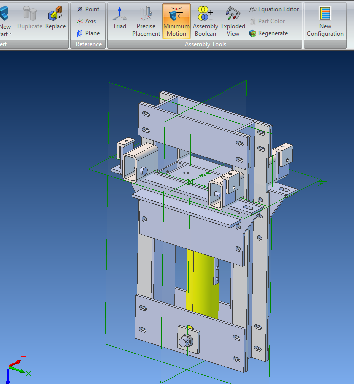
- FINGER AND SLOT CONSTRUCTION DESING FOR GUIDE ASSEMBLY
TUES NOV 19
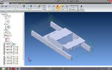
- DESIGN PROPOSALS FOR SOIL DRAWER GUIDE, PROPOSAL 1 COMPLETE
SAT NOV 16
- PREPARING FINAL DRAFT AND BILL OF MATERIAL
THU OCT 23
- TWEAKING MAIN FRAME ASSEMBLY, HOLES, ETC.
- 2D ROUGH DRAFT COMPLETE
- Media:01-001-00-5 10-23-13 ROUGH DRAFT.PDF
WED OCT 16
ceb 2d drawings
SAT OCT 12
backhoe drawings just incase it might help someone
FRI SEP 27 - SAT OCT 5, 2013
- Departed Sep 26 for FeF to help with microhouse build, arrived Fri 27. Left to return home 10/4, arrived home on 10/5.
WED SEP 18, 2013
- WORKING ON 2D DRAWINGS FOR CEB (DETAILS FOR MAIN FRAME ASSEMBLY)
TUE SEP 11, 2013
- WORKING ON 2D DRAWINGS FOR THE PAST FEW DAYS
- NEED TO GO BACK AND PUT IN MATERIALS
- NEED MASTER BOM
FRI Aug 30, 2013
- Revised placement of soil grate
THUR Aug 29, 2013
- Soil Drawer Example - File:Soildrawerassy.pdf
- modified wiki page for "cad standards" (part naming)
- ceb press model/drawings
Aug 26-28, 2013
- Organizing subassemblies
- 2d drawings
examples (unfinished): File:Main assembly example.pdf File:Main assembly example 2.pdf
SUN Aug 25, 2013
- STARTED WORK ON 2D DRAWINGS
TUE Aug 20, 2013
- PLACED PARTS AND UPDATED THE MODEL FOR THE CONTINUOUS HINGES (HINGE LENGTH?)
WED Aug 14, 2013
- Finished inserting all cnc cut parts into the 3d model
- the existing compression chamber spacer does not seem to fit the mounting holes in the new cnc cut part.
TUE Aug 13, 2013
- 3D MODEL HOPPER ASSEMBLY
SAT Aug 10, 2013
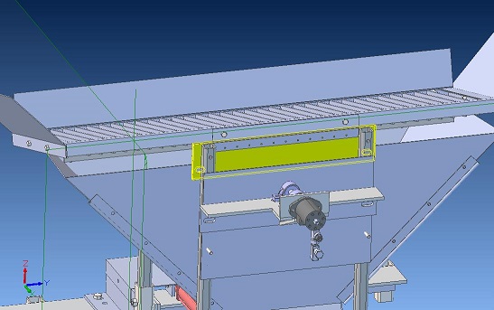
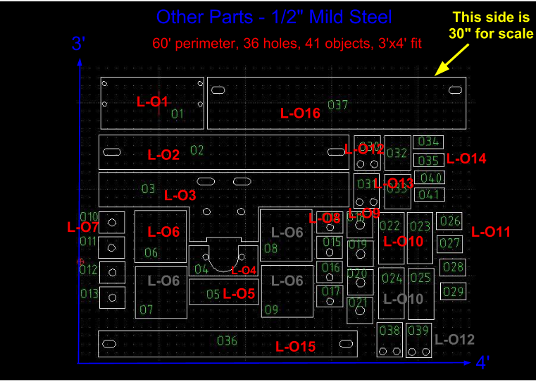
- I'm not sure how to place items L-O15 and L-O16, see pic below as to my guess (yellow part), but it appears that these new parts are wider than the hopper supports,I'm sure I'm missing something.
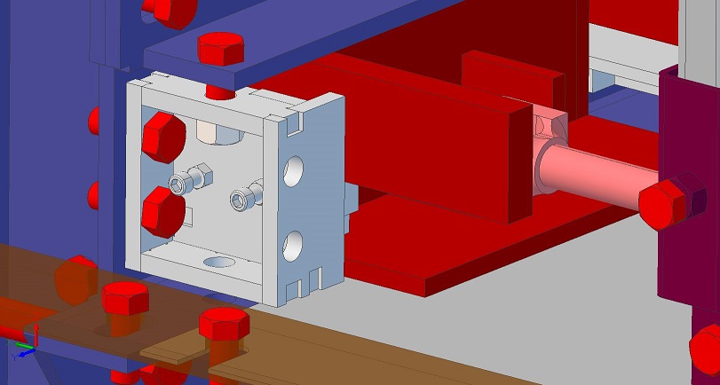
- I'm not sure how parts L-O12 and L-O14 are placed to make the valve mount, maybe someone has a picture.
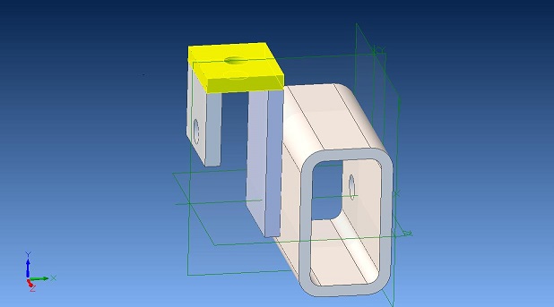
- I may have placed item L-O7 in the wrong place, see pic below (yellow part)
Thu Aug 8, 2013
- MADE 3D MODEL - CAM CLAMP ASSY
- HAVE QUESTIONS ABOUT SENSOR CLAMPS
- HAVE QUESTIONS ABOUT VALVE MOUNTING CLAMPS
- NEED PICTURES OF ALL THREE INCLUDING CAM CLAMPS
TUE, 6 Aug
- CEB V SOIL SHAKER 3D MODEL
MON, 5 Aug
- CEB V Hopper Supports 3d model
SAT, 4 Aug
- CEB V Arm assemblies 3d model
THU, 1 Aug
- CEB V drawer
Wed, 30 Jul
- CEB V frame - modified model for frame to reflect cnc cut parts.
- Finished core assembly, drawer assembly next
Mon, 29 Jul
- CEB V frame - modified model for frame to reflect cnc cut parts.
- still need to assemble top flange assembly
- Christmas_Gift_to_the_World
