Fibre Reinforced Pipe 3D Printer
Fibre Reinforced 3D printed Pipes
An experimental specialist concept for rapid protototyping of vehicles and other structurally strong space frame shapes such as furniture and buildings.

http://img.youtube.com/vi/xuXB4aWmcDk/0.jpg
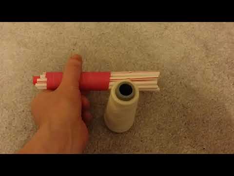
Basic concept is to wrap continuous strand fibre round a former then 3D print a single layer of plastic and interleave those.
Rationale is that space frames and geodesic shapes (including buildings and tents) with light weight pipes can easily be constructed with very efficient use of materials, not requiring solid infill yet still retaining high rigidity and structural strength.
- the CNC lathe part rotates a metal "former" around which you wrap paper (or duct tape) by hand, to start off
- a bobbin with kevlar (or hemp) twine is moved along as the CNC lathe part turns the former.
- on reaching the other end the bobbin direction reverses in order to create cross hatching. repeat a few times.
- the bobbin winding stops and the 3D printer takes over, laying down a layer of 3D printed material over the twine by moving the printer head in the X direction along the length of the former and covering the twine
- however instead of moving the pipe in the Y direction, the *CNC lathe* motor *rotates* the pipe.
- more filament is added until a full rotation is completed and the twine entirely encased.
- another crosshatch of twine is added using the CNC lathe
- the 3D printer part increases Z layer height as usual and adds another layer of plastic.
in this way an extremely strong and lightweight pipe is constructed extremely quickly that should have similar mechanical properties to carbon fibre tubes.
twisting strength along its length, due to the crosshatching, should also be extremely high.
for eco conscious projects, hemp fibre twine can be considered.
(question: Carbonised to carbon fiber via a kiln or similar device? reformed cellulose (ie rayon) also could work as is or carbonized. answer: if in the plastic as chopped fibres, yes. however also needed is full continuouw twine, for crosshatching, and cutting it or heat treating that may not be good)
for increased strength, fibre reinforced 3D filament can be considered.
for increased speed, 1.2mm or greater volcano E3Dv6 nozzles cwn be considered, although only for large ID tubes due to the need to have multiple interwoven layers.
TODO details, such as considering epoxy resin at the start and end of pipes
TODO, embedding metal screw threaded fittings into the ends of the pipe as it is formed, to aid in rapid assembly and construction of frames.
Julia Car
- fibre reinforced pipes, kevlar strands crosshatched sandwiched between layers of CNClathe rotated 3Dprinting
- M10 threaded pipe left at one end right at the other is embedded INTO the plastic and of course wrapped with lots of kevlar strand.
- Divergent3D "nodes" 3D printed fibre reinforced plastic, into which pipes are simply screwed.
- Calfee Design technique (bamboo bike with epoxy soakee cloth wrapping nodes) can be considered
- GABoats geodesic canoe using wood slats, more kevlar twine and heatshrink dacron for the outer skin
- and electric and downhill mountainbike parts are then used because the above only weighs 30 to 35kg even at a 5ft x 10ft x 4ft vehicle size.
- actual aluminium or metal parts is drastically reduced, to fastenings, bolts, and intricate pieces etc. -UELVEs_MBC
Embedding Threads / metal swivels
There is clearly a need to have strong (stainless steel, high-carbon, cast) metal parts at the end(s) of the pipes. These may either be jointed-parts, steel "lock" parts, threaded parts etc. all of which have the fundamental requirement to attach the 3D printed pipe to something, usually termed a "node".
From the concept diagram and video above it should be clear that as long as the metal parts are hollow and may fit over the steel "former" bar down the centre of the pipe as it is 3D printed, then not only can the 3D filament (and the twine) be wrapped around the metal part, encasing it in both twine and 3D-printed plastic and ensuring that it is an integral part of the pipe, then because the metal part is hollow, the steel former rod (and the smaller former rods inside) can be pulled or will drop out under gravity from the centre of the finished pipe.
If this is *not* intended to be done (taking the former rod(s) out), for mechanical reasons, or if the end parts cannot be made hollow for some reason, then one alternative is to use a cardboard or other suitable former (perhaps a pre-existing plastic hollow pipe, or thin-walled metal tube) into which the steel end-parts are embedded or attached, prior to the twine-wrapping and CNC-lathe-style 3D-printing process.
With there being no way to remove the internal former if that is the case, the selection of a cardboard or plastic tube is to greatly reduce the weight of the final result. If metal rods are to be left inside the tube, then bearing in mind that they are not really intended to be attached *to* the pipe as it is being 3D-printed, they do not contribute much to the structural strength, and, worse, simply increase the final weight.
Design and practical construction issues
One of the key reasons for using a metal former (particularly a solid bar) is because of concerns about the pipe "sagging" under its own weight as the 3D pipe is being printed. If cardboard, thin steel tube or a pre-existing plastic pipe is utilised as the "internal former", the concern is that this may not be rigid enough, particularly when considering 3D printing pipes over a metre in length and of narrow OD (15mm or less).
One idea considered was to have a pair of "roller tracker balls" as part of the frame, just underneath where the 3D printer head operates, on which the 3D-printed pipe would sit. The reason for having track-ball-style rollers is because the pipe not only needs to move back and forth in the X-axis, it needs to be *rotated* about the X-axis using the CNC-lathe Stepper Motor, as well, thus requiring *two* degrees of freedom of motion in addition to providing support for the 3D-printed part.
However, here, we see an inherent problem: as the pipe is being 3D-printed, it will *increase in outer diameter*. This would have to be taken into consideration, i.e. the gcode-generator, would have to be fully-aware of the geometry of the machine *and* the construction. As an alternative - for a first iteration - it would be far simpler to not have to do this, and to stick to high-rigidity low-density internal former material (perhaps even titanium or solid carbon fibre).
TODO
- track down suitable fibre reinforced filament
https://www.proto-pasta.com/products/high-temp-carbon-fiber-pla-composite https://markforged.com/product/kevlar-cff-spools/
Comments
- If kevlar is cost prohibitive, spring steel wire appears to be cheap and still 1/3 the tensile strength (150 ksi) (lkcl: or hemp twine. it's ecologically sound and highly effective. multiple strands will need to be wrapped around for cross-hatching, anyway).
- Divergent3D nodes - need thread swivels on one end. Is there a plan for this? (yes, a threaded pipe - one left-hand, one right-hand, can be put over the steel former and then integrated into the 3D print. special section on this TBD).