Steam Engine Specifications
Jump to navigation
Jump to search
Main > Energy > Steam Engine
Summary
- Deliverable: a one cylinder prototype module with scalability, to constitute a single stage of a stageable system (compound or 3 stage) which uses the same module that is scaled to make other stages
- System consists of cyliner, crank arm, mechanical valve, automatically adjusted cutoff ratio, and constitutes a Steam Engine Construction Set
- Cutoff ratio controlled by closed loop electronic feedback with some type of linear actuator
- Applications to stationary, mobile, and solar power
Cost-Related Features
- Lowest materials cost for a given performance
- Simplest to fabricate, therefore lowest fabrication cost
- Advanced techniques of fabrication utilized only when necessary to achieve cost
- Fabrication tooling preferably simple, but secondary to fabrication cost
- Uses commonly available parts
- Replicable
- Materials cost of $50/hp
Materials Calculations
- 20 pounds of weigh per horsepower
Flexibility and Performance
- Scalable in power output from 1 - 100 hp by scaling or adding modules
- Power density of 1 hp/10 lb
- Pressure up to 500 psi
- Scalable cylinder dimensions, uncoupled staging, and tandem operation allows scaling of power and eficiency from 1-100 hp and up to 25% efficiency
- Multiple cylinder, in-line configuration is possible by bolting several cylinders together
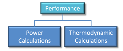
See the following for steam engine calculations:
- Steam Engine Construction Set Calculations
- Steam Engine Efficiency Calculations
- Steam Engine Efficiency
Lifecycle
- Long lifetime under continuous use (50 years)
Ecology
- Compatible with stationary, solar, and mobile power applications
- LifeTrac power source
- Solar Power Generator heat engine
- CHP with space heating
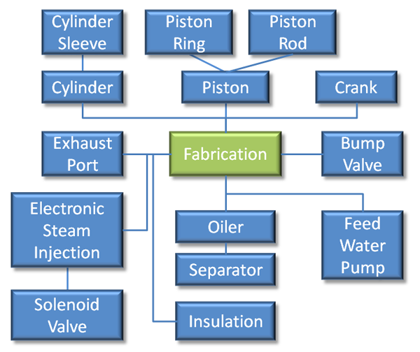
Fabrication
Steam Engine Elements:
- Elements to be Purchased
- Cylinder Assembly
- Cylinder Liner
- Cylinder Bolts (4) - 3 sizes
- Water Drain Plug
- Exhaust Plenum Bolts (4)
- Piston Assembly
- Piston Rings (2)
- Valve Assembly
- Valve Springs (2)
- Valve Spring Bolts (2)
- Base Plate Bolts (4)
- Cylinder Assembly
- Elements to be Fabricated
- Cylinder Assembly
- Cylinder
- Cylinder support assembly
- Cylinder end cap with valve seats
- Cylinder end cap and end mount
- Exhaust Plenum - 2 pieces
- Piston Assembly
- Piston Head
- Bump Valve Pins (2)
- Piston Connector Rod
- Valve Assembly
- Valves (2)
- Base Plate
- Oil Dribbler
- Cylinder Assembly
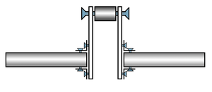
Crankshaft Elements:
- Crankshaft
- Shaft pieces (2)
- Offset plates (2)
- Crank piece (1)
- Couplers (2)
- Screws
- Crankshaft support assembly
- no welding in this design.
- does require tapping holes for machine screws.
- needs counterbalance to not vibrate.
Techniques and Stock:
- Casting used for body
- Stock parts wherever feasible
- Lathing for bore
Other:


