Steam Engine Build/Valve Cover
Main > Energy > Steam Engine
Steam Engine Build Instructions
Description
The valve cover serves the following functions:
- Holds the valves in place
- Holds and aligns the valve springs in place
- Shelters the valve springs from steam heat
- Steam input vent
- Bolted to cylinder end cap
- Bolted to mounting bracket
Because of the size of the valves and valve springs, the valve cover is quite thick along the engine center line axis. Eventually, this part should be molded in cast iron. To simplify initial fabrication, the valve cover is built up from the three pieces of metal, welded together.
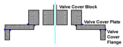
The valve cover consists of three sub-parts welded together as shown in the drawing (not to scale) above:
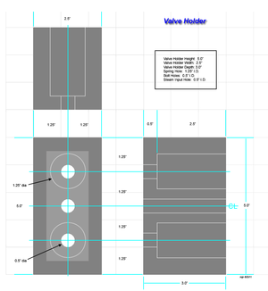
- Valve Cover Holder
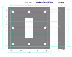
- Valve Cover Plate
- Valve Cover Flange
Drawing
Instructions
1. Initial Valve Holder Fabrication
(instructions here)
2. Initial Valve Cover Plate Fabrication
(instructions here)
3. Weld Test
Welds attaching the block to the plate are critical because they must be absolutely air-tight or steam will escape. Worse, superheated steam will erode steel if it flows through a narrow channel (leak). The best way to test this to fabricate the cylinder valve seat (see Steam Engine Build/Cylinder Valve Seats, but omit milling of the valve seats. This allows the cap to be bolted to the valve cover plate with only the steam vent drilled.
(block/plate sub-assembly for weld test)
The steam vent can then be used to pressurize the steam chest (gap between the valve cover and the cylinder end cap). Soap brushed over the welds should reveal leaks. For additional testing, immerse the test assembly into a pan of oil and repeat the pressure test looking for bubbles formed. Assuming a source of air pressure equal to estimated steam pressure (150psi), this will verify steam-tight welds.
4. Drill Valve Holes
(block/plate sub-assembly with valve holes shown)
5. Flange Fabrication
- Cut four rectangular pieces of half inch plate steel 1.0" wide by 8" long.
- Weld them to the back of the valve cover plate.
6. Final Valve Cover
(full drawing here)


