D3D Australia
Basics
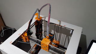
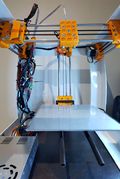
- This is a replication of the D3D 3D Printer
- It was made in Emerald, in the Central Highlands region of Queensland. Australia.
- It was made by Germán Crespo on 24/01/2018. See German Log
- It used the metal frame option.
Data Collection
- Good print results:
BOM D3D Australia
Log:
Sun Feb 11, 2018
Printing
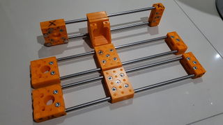
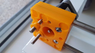
- Printed the first set of short idler side parts for the D3D printer. Prints are aesthetically acceptable and the dimensions are accurate.
Fri Feb 09, 2018
Printing
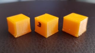
- Printed four more cubes and one cone. Prints are of acceptable quality. Dimensions are accurate. Some more refining can be achieved.
Troubleshooting
- I had to reinstall Cura LulzBot Edition but only managed to find Version 2.6.66 which has a different interface to the version I had become familiar with, although it offers a wider variety of options to tweak the prints.
- I tried several different options to eliminate the issue with the squashed bottom layers. Things I tried and DID NOT work:
- Increasing voltage on stepper motors' drivers.
- Changing steps/mm configuration for the Z-axis. Increased it from 80 to 83 steps/mm. This had an effect in making the irregularities disappear from the lower parts of the prints but increased the overall height of the pice by some 10%.
- Changing computers and OS.
- What DID work:
- Changing acceleration value for Z from 100 to 1000.
- Edditing start G-Code in Cura.
Notes
After reinstalling Cura, I decided to go with the start G-Code already written in the software. This script only had a few lines and did not include ABL (auto bed leveling). I printed two cubes in this configuration and noticed that the squashed bottom layers had almost disappeared from the prints. I then added the ABL to the code but left the rest unchanged. Prints where good but it seems that for some reason adding ABL to the code created ripples/shadowing/ghosting in the side of the cubes.
Preset G-Code for Cura V2.6.66
G28  ;Home
G1 Z15.0 F6000  ;Move the platform down 15mm
;Prime the extruder
G92 E0
G1 F200 E3
G92 E0
Issues to resolve
- There is a fair bit of shadow/ripple/ghosting on the printed pieces.
Tue Feb 06, 2018
Assembly
- Finished geometry rearrangement. Extruder nozzle and inductive sensor holder.
Printing
- Printed eight test cubes with varying degree of success.
Issues
- Ubuntu prompted me to update some software, which I did. In the process, Cura was updated and it changed to the standard version, which was not working on my computer.
- The issue with the squashed bottom layers remain. The printed pieces show rough sides around the lower part and are shorter in height.


Fri Feb 02, 2018
Assembly
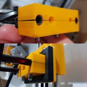
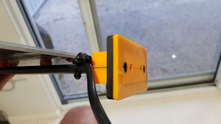
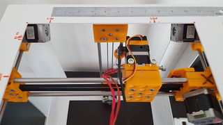
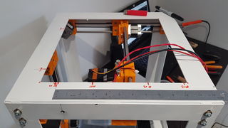
- Rearranged X-axis, PSU, HBP and control board to suit OSE's standard geometry for this machine. This involved the drilling of two extra holes on the frame to displace the Z-axis towards Y2 and the removal and regluing of the HBP from its supporting rods. The end stops on both, X and Y-axis needed modifications also. See images.
- Changed Z-axis motor in an attempt to fix the issue with the squashed bottom layers.
Notes
Having the abovementioned circumstances in consideration and thinking back on the original assembly described in this log, I would recommend placing the installation of the Z-axis and HBP as the absolute last step in the assembly process. This at least until an accurate, standardized, position for the holes on the frame can be established.
Correct Geometry.
Positioning holes on Z.
End Stop X
End Stop Y


Tue Jan 30, 2018
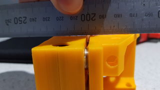
Printing
- Test printing. Finally managed to get the resolution on the base of the cone (see pictures). I had to change the steps per millimeter configuration on the z-axis to achieve this result. I did it by adding an M92 code line in Cura's Start GCode. I changed it from 80 steps/mm to 83 steps/mm, although 82 steps/mm could be a better approximation.
- Printed a rectangular frame to fit around the short idler side sandwich that holds the HBP. This frame is a quick fix to add mechanical strenght to the HBP support and keep the sandwich closed tight around the rods.
Notes
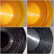
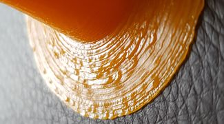
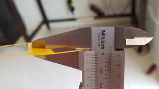
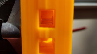
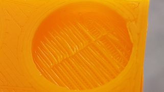
- After printing several test cubes and cones, I did something that I had neglected doing up to that point: measured the dimensions of the prints with the vernier caliper. I came then to the realization (at least for now) that the issues that I was having on the Z-axis (squashed layers) were related to the increments on the movement of the axis being shorter than expected and the nozzle was rubbing on the previously extruded layer of the print and that the fused material of each newly deposited layer was being squeezed to the sides of the nozzle path. See image with test cones' top view (shape of a witch hat).
Reinforcing frame. HBP support.
Steps/mm on Z.


Wed Jan 24, 2018
Printing
- First day of test-printing and the machine performs very well considering where we come from. I have printed four cubes and three cones as guides to have an idea of the possible modifications needed. A few details need attention.
- Solved yesterday's issue with three point probing. For some reason the GCode in Cura had change. In the following table you can see the lines added to get the probing going once again:
| Before | After |
;Sliced at: {day} {date} {time}
G21 ;metric values
M117 Printing... |
;Sliced at: {day} {date} {time}
G21 ;metric values
M117 Printing... |
Issues to resolve
- There is too much oscillation in the heated bed on the X-axis. This is caused by the momentum generated by the movement of the carriages along the axes. I will work on the HBP attachment to the Z carriage to try to reduce it.
- The first ten or so layers are being squashed by the extruder nozzle.
Notes
I have modified the voltage on the Pololu drivers. Raised it from 0.6V to 0.8V.
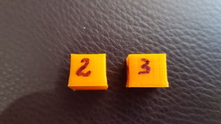
Two cubes.
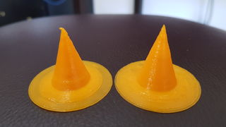
Two cones (witch hat)
Cone, side.
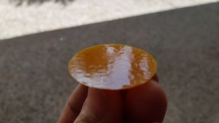
Cone, base.
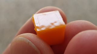
Cube, bottom.
Three cubes.
Three cubes.
Layer thickness.
Base layer.
Layer, bottom.


Tue Jan 23, 2018
Software
- Worked on Marlin firmware's values for probing points, travel limits after homing and extruder offset. The order that I consider correct to work on these three points is as follows:
Within Arduino IDE --> configuration.h -->
1- Travel limits after homing: Do this one first to make sure that the X and y axes' carriages stop before overshooting their maximum physical travel limits on the side opposite the end stops. This also defines the limits of your HBP area. The limits set in Cura while setting up the D3D machine profile did not work for me.
// @section machine

// Travel limits after homing (units are in mm)
#define X_MIN_POS 0
#define Y_MIN_POS 0
#define Z_MIN_POS 0
#define Y_MAX_POS 190    //Changed this value from 250 GC
#define X_MAX_POS 200    //Changed this value from 250 GC
#define Z_MAX_POS 200    //Changed this value from 250 GC
2- Auto Bed Leveling (ABL) probing points: Once your maximum travel limits (bed area) are set, you guarantee that you cannot accidentally set these probing points outside the bed area in the firmware. If you set up a point that falls outside the bed area, a warning message will be displayed in the Arduino Sketcher when you verify the code. These points are simple cartesian coordinates but it could get tricky if you don't have a clue of where the imaginary origin of the coordinates is on the surface of your bed. In the case of this machine, with the default settings, the origin of coordinates (0,0) is on the front right corner of the machine, opposite the HOME position on Y.
#elif ENABLED(AUTO_BED_LEVELING_3POINT)

// 3 arbitrary points to probe.
// A simple cross-product is used to estimate the plane of the bed.
#define ABL_PROBE_PT_1_X 40     // Changed this value from 40 GC
#define ABL_PROBE_PT_1_Y 20     // Changed this value from 200 GC
#define ABL_PROBE_PT_2_X 105    // Changed this value from 40 GC
#define ABL_PROBE_PT_2_Y 190    // Changed this value from 40 GC
#define ABL_PROBE_PT_3_X 170    // Changed this value from 200 GC
#define ABL_PROBE_PT_3_Y 20     // Changed this value from 40 GC
3- Extruder offset: This is the final step to ensure that you can utilize the whole of the printing area right to its boundaries. In this machine the inductive sensor is offset 14mm to the back (towards Z) and 38mm to the left (towards Y1) of the extruder nozzle. With this in consideration, and following the guidelines set by the box drawn on the left, the values to input in the lines under the boxes below should be: X OFFSET -38 and Y OFFSET 14. But note that the boxes below are mirror images and it is the box to the right the one that represents the actual configuration in this printer. As such, the sign for the X offset value remains positive.
//    +-- BACK ---+                           +-- BACK ---+
//    |           |                           |           |
//  L |    (+) P  | R <-- probe             L |    (+) P  | R <-- probe
//  E |           | I                       E |           | I
//  F | (-) N (+) | G <-- nozzle            F | (+) N (-) | G <-- nozzle
//  T |           | H                       T |           | H
//    |    (-)    | T                         |    (-)    | T
//    |           |                           |           |
//    O-- FRONT --+                           +-- FRONT --0
//  (0,0)
#define X_PROBE_OFFSET_FROM_EXTRUDER 38  // X offset: -left  +right  [of the nozzle]   Changed from 20 GC
#define Y_PROBE_OFFSET_FROM_EXTRUDER 14  // Y offset: -front +behind [the nozzle]      Changed from 10 GC
#define Z_PROBE_OFFSET_FROM_EXTRUDER -0.05
Notes
I struggled to find a physical reference to match with what the values in the firmware where indicating. Part of the problem was that the imaginary +X of the cartesian coordinates on the HBP is inverted, that is, it increases in value to the left, as explained above. This discrepancy is associated with the difference in the geometry of this machine compared with OSE's standard. The motor on the X-axis should be on the Y1 side.
Attention: If you decide to modify the firmware and check each one of these steps on the machine before continuing with the following one, keep well in mind that the inductive sensor is offset from the nozzle and you will have to be ready to pull the plug from the wall if you see it falling outside the bed while proving.
Issues to resolve
The machine is not probing the three points anymore. I suspect that there could be a hiccup in the Marlin firmware or in the GCode in Cura. This happened suddenly, for no obvious reasons.


Fri Jan 19, 2018
Troubleshooting
Worked on yesterday's problems:
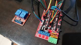
- All issues with the axes were resolved after installing the jumpers underneath the Pololu drivers.
- To solve the issue with the HBP, the relay module was left connected to D8- and both trigger jumpers were swapped to trigger on Low. I was getting an error message in Cura that read like this:
< Error:MINTEMP triggered, system stopped! Heater_ID:bed

< Error:Printer halted. Kill() called!
This message was due to a faulty thermistor installed in the heated bed.
Notes
Two temperature values should be displayed automatically on the title bar of Cura's control panel when the printer is connected: one for the bed and the other for the extruder. When the power is off, both values are going to be very similar to each other and close to room temperature. If one or no value is displayed, then there is a problem with the signal from the thermistor and you need to find the fault.
Issues to resolve
- Firmware. Printing area and Z-probe offset from extruder nozzle.
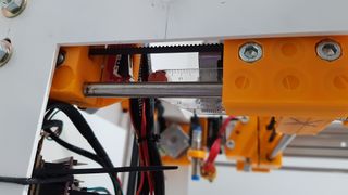
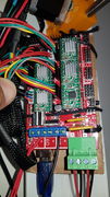
Jumpers: 4 out of 15 in this picture.


Thu Jan 18, 2018
Wiring
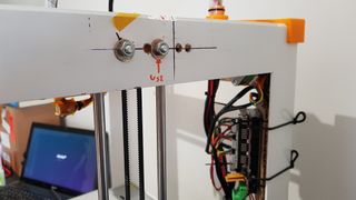
- Finished routing wires.
Software
- Worked on uploading Marlin firmware to the Arduino board and tried to set up the printer.
Printing
Finished design and printed alternative to cable chain.
![[1] Cable Bundler on X - SIZEk - FreeCAD -File:D3D cable bundler x.fcstd. STL - File:D3D cable bundler x.stl](/images/thumb/2/20/D3D_cable_bundler_x.jpg/120px-D3D_cable_bundler_x.jpg)
 [1] Cable Bundler on X - SIZEk - FreeCAD -File:D3D cable bundler x.fcstd. STL - File:D3D cable bundler x.stl
![[1] Cable Bundler on Frame A - SIZEk - FreeCAD - File:D3D cable bundler frame A.fcstd. STL - File:D3D cable bundler frame A.stl](/images/thumb/4/46/D3D_cable_bundler_frame_A.jpg/120px-D3D_cable_bundler_frame_A.jpg) [1] Cable Bundler on Frame A - SIZEk - FreeCAD - File:D3D cable bundler frame A.fcstd. STL - File:D3D cable bundler frame A.stl
[1] Cable Bundler on Frame A - SIZEk - FreeCAD - File:D3D cable bundler frame A.fcstd. STL - File:D3D cable bundler frame A.stl
![[1] Cable Bundler on Frame B - SIZEk - FreeCAD - File:D3D cable bundler frame B.fcstd. STL - File:D3D cable bundler frame B.stl](/images/thumb/5/57/D3D_cable_bundler_frame_B.jpg/120px-D3D_cable_bundler_frame_B.jpg) [1] Cable Bundler on Frame B - SIZEk - FreeCAD - File:D3D cable bundler frame B.fcstd. STL - File:D3D cable bundler frame B.stl
[1] Cable Bundler on Frame B - SIZEk - FreeCAD - File:D3D cable bundler frame B.fcstd. STL - File:D3D cable bundler frame B.stl
![[1] Cable Bundler on X - SIZEk - FreeCAD -File:D3D cable bundler x.fcstd. STL - File:D3D cable bundler x.stl](/wiki/File:D3D_cable_bundler_x.jpg)
![[1] Cable Bundler on Frame A - SIZEk - FreeCAD - File:D3D cable bundler frame A.fcstd. STL - File:D3D cable bundler frame A.stl](/wiki/File:D3D_cable_bundler_frame_A.jpg)
![[1] Cable Bundler on Frame B - SIZEk - FreeCAD - File:D3D cable bundler frame B.fcstd. STL - File:D3D cable bundler frame B.stl](/wiki/File:D3D_cable_bundler_frame_B.jpg)
Issues to resolve
- X and Y axes move freely by hand but are not working when powered using the control panel in Cura. The motors receive power but instead of moving one way or another they are locked in place.
- There is a lot of vibration on the belt of the Z-axis on the side where the peg holds the belt to the carriage. One can also hear a noise. This happens while manually operating the axis using the printer control panel in Cura. The interesting thing is that if I use the bed leveling function from the top menu, the noise and vibration disappear. Also, the actual range of movement of the bed is much larger than the indicated values on the screen: if I send a signal to move it by 10mm, it actually moves 160mm millimeters.
- The relay module is being constantly powered by the RAMPS and the heated bed heats up to max temp all the time. I tried swapping the cable to the minus (-) connector on D8 but both terminals (+ and -) seem to be powered all the time (not quite).


Wed Jan 17, 2018
Wiring
- Routed more wires in the machine.
- Started designing an alternative to cable chain to route the wiring for the X-axis. The length of the stepper motor cables that I currently have is not enough to use with the cable chain. This design will use a commercially available plastic spiral wrap to keep the wires out of the way of the moving parts.
Notes
- During this stage, it is very important to make sure, to double check, that you are connecting the wires as specified on slides 2, 3 and 4 in this link: Wiring
- Important: You have 15 jumpers that come whit your RAMPS. They Must be installed under the Pololu drivers, three jumpers under each driver.


Fri Jan 12, 2018
Assembly
- Glued heated bed to the holder and attached it to the carriage on the Z-axis.
Wiring
- Routed HBP power wires to relay module and PSU.
- Wired and installed relay module.


Printing
- Designed and printed insulating box for relay module.
- .pngRelay Module Insulating Box - SIZEk - FreeCAD -File:NAME.fcstd. STL - File:Relay box.stl
Tue Jan 09, 2018
Assembly


Notes
To be edited:
- Attempt to insulate heated bed
Mon Jan 08, 2018
Assembly
- Cut heat-resistant rubber to use as a spacer between heated bed and bed rods.
- Rearranged end stops to shorten the length of travel on Y and lengthen it on X.
- Installed step motor controllers on RAMPS board.
- Adjusted X-axis so it is parallel to frame.
Notes
To be edited:
- Check squareness on X-Y and X-Z when installing X
- Rubber used is recycled from scrap. Maybe tyre rubber could do the job. The only limitation is temperature.
- End stops modified searching for ideal travel range on X and Y.


Sat Jan 06, 2018
Assembly
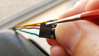
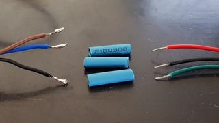
- Grouped the controller-end of the extruder and heated bed termistors in a single PHR-4 connector. It is a bit harder to remove the wires from this type of connector than from the Dupont ones, but still doable.
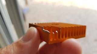
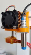
- Installed sensor holder on extruder. I recommend you to trim the vanes of the heatsink only to the point where you can fit the sensor holder underneath the cooling fan. By doing so, you are ensuring that there is still a good amount metal in that area to take away the heat from the assembly and to provide separation between the sensor holder and the base of the heatsink. Language agnostic instructionals for this assembly, here.
- Marked on the frame the range of movement available on the X and Y axes to have an idea of the printable area size and position.
Notes
The current position of the stepper motor on X is towards Y2 and front side. With this configuration, I get a maximum range of travel on X of 7 1/2in (191mm) and of 7 3/8 in (188mm) on Y. The aim is to increase the range to 8in on both axes. Also, the Z-axis will need to be offset towards Y1 to compensate for asymmetry on X-axis configuration.
[[Note vanes where trimmed but not removed
191mm
188mm


Wed Jan 03, 2018
Assembly
- Trimmed 2mm from M6x30 SS screws. These screws were slightly longer than needed and were jacking the nuts against the outer wall of the catchers on the idler and motor side of X and the bed dupport on Z.
- Finished the assembly of the X and Y axes and attached them to frame. A reference for tightening the belt: set the carriage halfway along the its axis and press both sides of the belt with your index finger and your thumb until you feel a noticeable amount of resistance. If the gap is of around about 8 to 10 mm, then it's tight enough
Printing
- Printed belt pegs for carriages. I changed the orientation of the pegs on the .stl file and printed them with the shortest leg at the base to avoid bridging along the belt slot.


Mon Jan 01, 2018
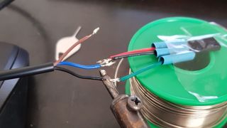
Assembly
Worked on the wiring of the controller. Changed the sequence of the wires on a PHR-4 terminal and soldered the wires of the Dupont connector from the extra end stop to the inductive sensor's wires. Connected the cables for all the axes, end stops, Z probe and extruder motor to the controller.
Changing the order of the wires on a Dupont connector
Wiring set up for inductive sensor


Sat Dec 30, 2017
Assembly
- Soldered wires to HBP. Minimum soldering iron power should be 40 Watt, and you need patience. Tested the heated bed by connecting it directly to the power supply. The maximum temperature reached was 105 deg centigrades.
- Deburred some of the 3D printed parts (bridged filaments from nut/screw sockets) and assembled axes y and x.
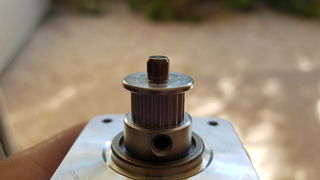
- Installed pulleys on stepper motors. An easy way to go about this task is to use something like one of the idler bearings as a reference for the placing of the pulleys. I placed the bearing on top of the pulley and lined up the top face of the bearing with the bottom of the chamfer on the motor axle.
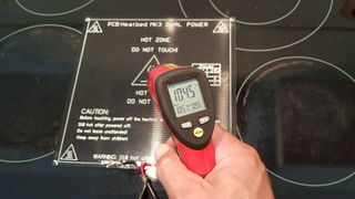
Maximum temp of HBP without regulation
Do not overtighten the center screw of the assembly
X and Y axes

Used a bearing as a reference to place the pulleys
Correct placement of pulley
Correct alignment


Thu Dec 28, 2017
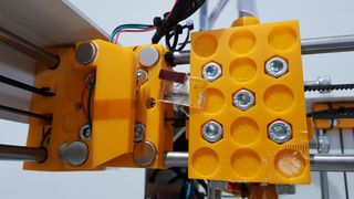
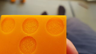
Assembly
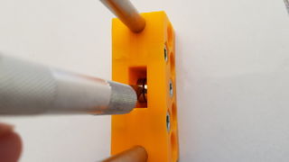
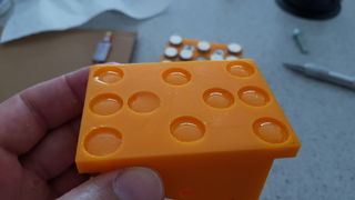
Gluing magnets to x-axis carriage and extruder motor interface. You will need some tape (stationary type), cyanoacrylate or epoxy glue, a flat steel surface (top of your fridge, for example), something heavy (books), printed carriage and extruder interface parts and magnets.
Best advisable way to do this is as follows:
- Make sure that the surface in the bottom of the magnet sockets of both parts is going to provide a solid base for the glue. In my parts, I had a first layer of extruded PLA that was not strongly bonded to the next layer so I scraped the bits that were loose with a blade. See pictures.
- Glue the magnets on the carriage side first. It's better if you have the carriage already assembled so any irregularity in the plane shared by the magnets can be corrected by the gluing process. If you are using epoxy, as I did, to glue these magnets in one attempt you will need to use some stationary or packing tape. I recommend you also to practice placing the magnet without glue first to have an idea of their behavior. It will be frustrating at first. Place a drop of epoxy in all the slots, make sure that it will be enough to climb up the sides and fill the gap between the magnet and the wall of the slot. Start placing the magnets in the slots from either the top or bottom side of the carriage and complete one row at a time. There are 5 rows. Skip rows 2 and 4 (single magnet rows) on your first pass to make the job easier. As you finish placing the magnets in one row, use a bit of tape to hold them down and then move to the next row. Make sure that there are no wrinkles on the surface of the tape. Remember that the magnets have to be placed in the same orientation.
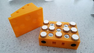
- Once all the magnet are placed and hold down by the tape, find your flat metal surface and stick the carriage to it adding a few books on top for pressure. It is better if you find a flat bit of steel that you can sit on top of the carriage to stop the glue from running out of the receptacles.
- Once the glue has cured, remove the tape and scrape any excess glue from the surface of the magnets. Proceed then to stick the motor interface's magnets to the magnets already glued on the carriage side. Place a drop of epoxy in all the slots of the extruder interface and lay it down on top of the carriage. Line up/square the edges of both parts, flip the assembly around and sit it on top of one of the motor assemblies (with the motor on it) to dry. Don't forget to put some books on top. By doing this you are ensuring both, a perfect axial alignment of the poles of all magnets and of all the magnets' surfaces on the plane.
Lack of adhesion between layers due to bridging
Before and after scraping
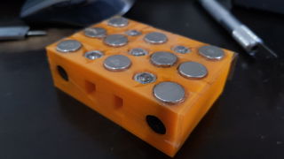
Magnets held down with tape
Placing magnets for extruder interface
Beads of epoxy on extruder interface
Proper alignment


Printing
Sensor holder, end stop interfaces and flanges for idler bearings.

Wed Dec 27, 2017
Assembly
- Drilled holes in the metal frame.
- Put together one of the axes assemblies and test fitted it to the z-axis and y-axes holes to check for alignment, spacing and freedom of movement of the carriage.
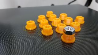
- To mount the axes in this fashion is necessary to replace 12 of the M6x18mm Cap Screws by 12 M6x30mm Hex head screws in the BOM. 12 Washers can also be included.
Hole marks
Misplaced holes and correction
Spacers
Spacers motor side
Spacers idler side


Notes
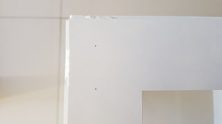
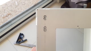
- After using the 3D printed template to place the marking of the holes, and after drilling the holes, I realized that the carriage sandwich has an overall height that is 8mm larger than the end idler and motor assemblies. This offsets the top and bottom of the carriage by 4mm in relation to the two ends of the axis assembly. I repositioned all the holes down by 6mm and redrilled to accommodate for this hiccup (4mm would have sufficed but I went with 6 to be able to drill next to the other holes)
- After printing the spacers to fit the axis assemblies to the frame, I came to the realization that I had forgotten the existence of the nut catchers in the idler and motor side sandwiches. I am not sure at this stage if I should have aimed to mount the axes using these catchers. Since I had already made my mind about mounting the axes using two of the holes that press the sandwiches together, I decided to continue on that path.
Tue Dec 26, 2017
Assembly
- The spacers described under "Printing" are not necessary unless you do not feel like walking to the hardware store for some washers.
- Do not use the holes-template tool described under "Printing".
Printing
Printed and test fitted:
- Template to accurately place holes on metal frame.
- Set of 12 spacers to separate the bolted axes assemblies from the metal frame. Inbuild separation is 2mm.
![[1] Y-axes Holes Placement Template - SIZEk - FreeCAD -File:NAME.fcstd. STL - File:NAME.stl](/images/thumb/5/54/D3DAustralia_Holes_Template.png/120px-D3DAustralia_Holes_Template.png) [1] Y-axes Holes Placement Template - SIZEk - FreeCAD -File:NAME.fcstd. STL - File:NAME.stl
[1] Y-axes Holes Placement Template - SIZEk - FreeCAD -File:NAME.fcstd. STL - File:NAME.stl
![[12] Axes Spacers 2mm - SIZEk - FreeCAD - File:NAME.fcstd. STL - File:NAME.stl](/images/thumb/b/bf/D3DAustralia_Axes_Spacer.png/120px-D3DAustralia_Axes_Spacer.png) [12] Axes Spacers 2mm - SIZEk - FreeCAD - File:NAME.fcstd. STL - File:NAME.stl
[12] Axes Spacers 2mm - SIZEk - FreeCAD - File:NAME.fcstd. STL - File:NAME.stl
![[1] Y-axes Holes Placement Template - SIZEk - FreeCAD -File:NAME.fcstd. STL - File:NAME.stl](/wiki/File:D3DAustralia_Holes_Template.png)
![[12] Axes Spacers 2mm - SIZEk - FreeCAD - File:NAME.fcstd. STL - File:NAME.stl](/wiki/File:D3DAustralia_Axes_Spacer.png)
Notes
- The creation of these files served as a FreeCAD training exercise to me, and although the result is as I intended, the organization of the different elements inside the FreeCAD files leaves much to be desired.
- The template tool is, as from now, deprecated. The idea is good for a building workshop where many units are being assembled and if you have not gotten the holes cut on the frames. At this stage, nevertheless, the holes need to be repositioned to accommodate for the offset position of the carriage on the axis assemblies.
Sat Dec 23, 2017
Assembly
- Assembled carriages for the four axes (+- 15 min per assembly) and glued the magnets on the x-axis carriage. See notes for more details about this assembly.

Printing
Finished the design an printed a corner template to place marks on the metal frame where the holes that hold the axes in place are meant to be located. This tool provides an accurate way to place the marks for the holes on both the motor side and short idler side of the carriage on any corner of the cube. The file for this template has not been uploaded to the wiki yet since it needs a modification.


Notes
While putting the carriages together, one can notice that the linear bearings do not have a snug fit in the sandwiched assembly. I noticed this by shacking the assembly. To fix it, I have wrapped each bearing with two layers (two turns of the bearing) of clear packing tape. This increases the diameter of the bearings to between 15.15mm and 15.20mm. By doing so, one can reduce the amount of oscillation of the carriage during the operation.


Wed Dec 20, 2017
Assembly
Finished stitch welding the frame and painted it.
Notes

Tue Dec 19, 2017
Assembly
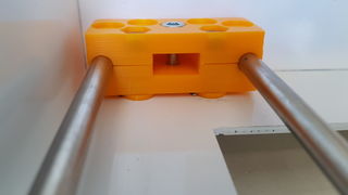
Removed brim from the new set of Carriage Side and assembled them. The carriages slide with no resistance on the shafts. Started cleaning the frame for painting and the epoxy glue started cracking in parts and separating from the frame in others. I am not sure about the reasons but it could be a combination of factors. I disassembled the cube and started from scratch. This time I decided to weld it with a TIG machine. I only tack welded it at this point.
Notes
The idea of the metal frame is appealing because of its structural rigidity, and one also needs to consider that it was designed with the use of magnets for the axes in mind. Nevertheless, I found the assembly of the frame to be a rather cumbersome process without a precise way of squaring the corners. I would consider alternatives in a future build. Used a ZAP brand clear epoxy glue for the frame's first assembly, for the record.
The 3D printed parts with the brim are pretty much perfect.

Mon Dec 18, 2017
Assembly
Assembled two carriages and checked the alignment of linear bearings on one of the assembled axes' rods. Bearings are slightly misaligned due to warping of printed parts.
Printing
Carriage Side parts are fairly warped, in part due to printer settings.
Created a new .gcode file for the Carriage Side to try to reduce the warping on these parts.
Printer settings for PLA plastic:
Layer height: 0.2mm
Shell thickness: 1.2mm
Bottom/Top thickness: 1.2mm
Fill density: 25%
Printing Speed: 50mm/s
Printing temp: 200 C
Bed temp: 50 C
Nozzle size: 0.4mm
These settings are, at this time, random aproximations based on basic configuration across different machine models for PLA.
Notes
Brought the printing settings back to default, reduced the HBP temperature to 50 deg C and added a brim in an effort to minimize warping.
Sun Dec 17, 2017
- Started this log.
Printing
Generated .gcode file for Carriage Side and started the printing process. Estimated printing time for one set of four parts is 11:00:00. Eight of these parts are needed (two sets with current .stl file layout).
Printer settings for PLA plastic:
Layer height: 0.2mm
Shell thickness: 1.6mm
Bottom/Top thickness: 1.5mm
Fill density: 25%
Printing Speed: 50mm/s
Printing temp: 200 C
Bed temp: 70 C
Nozzle size: 0.4mm
These settings are, at this time, random aproximations based on basic configuration across different machine models for PLA.
Notes
Sat Dec 16, 2017
Assembly
- Glued the last 16in square to the frame and trimmed excess epoxy (+-1 hour).
Printing
- Printed a second set of Motor Side assembly. Eight of these parts are now ready. Two for X-axis, four for Y-axis and two for Z-axis.
Printer settings for PLA plastic:
Same as previous day.
Fri Dec 15, 2017
Assembly
- Preparing (straightening bows, sanding of edges, degreasing), squaring and gluing of 16" D3D frame (+-4 hours). As with the first set of squares that I got cut out, all of these squares presented some degree ob bowing due, I believe, to the heat generated by the cutting process on a plate that, at 3mm, is relatively thin.
- Put together some of the axes' parts to check the squareness of the 8mm rods. Prints are very precise. Rods are parallel across all planes. Assembled HBP support. Possible issues could be sagging of the far end of the heated bed after some use and jittering of bed if Z-axis needs to work too hard for the auto leveling during the printing.
Printing
- Short Iddler Side printed successfully. Elapsed time: 09:43:00. Created .gcode file and started printing another set of parts: Motor Side Estimated printing time for one set of four parts is 10:20:00. Eight of these parts are needed (two sets with current .stl file layout).
Printer settings for PLA plastic:
Layer height: 0.2mm
Shell thickness: 1.2mm
Bottom/Top thickness: 1.2mm
Fill density: 30%
Printing Speed: 50mm/s
Printing temp: 200 C
Bed temp: 60 C
Nozzle size: 0.4mm
These settings are, at this time, random approximations based on basic configuration across different machine models for PLA.
Thu Dec 14, 2017
Printing
- First set of parts printed with a fault (shift on Y-axis position halfway through the printing process). Replaced end-stop micro switch. Checked motor driver. Swapped X-axis driver with Y-axis driver. The problem seems to be solved. Probably just a bad contact in the driver's connection. Created .gcode file for Extruder Holder. Extruder holder printed successfully. Created .gcode file for Short Idler Side. And started the printing process.
Printer settings for PLA plastic:
Same as previous day.
Notes
Bridging. There are strings of filament that did not anchor to the edges of the magnet's socket-bases and nut's socket-bases. The filament fell into these socket's space during the printing process. Part of the problem is due to gaps in the printed perimeter of the sockets. These gaps are the result of the proximity or intersection between the perimeters of various sockets with each other and with the outer shell of the part.
Suggestions
Check .stl and .fcstd files to try to solve this issue.
Wed Dec 13, 2017
I have all the parts required except for the 3D printed parts. I am printing my own parts and I will be learning the basics of the printing process as I move along. For this reason, this log will contain some details concerning printer settings that I will be trying with the different parts necessary for OSE's design. These settings may or may not be of use later on but are, I believe, a good reference point.
Printing
- Started printing first set of parts Motor Side.
Printer settings for PLA plastic:
Layer height: 0.2mm
Shell thickness: 1.2mm
Bottom/Top thickness: 1.2mm
Fill density: 25%
Printing Speed: 50mm/s
Printing temp: 200 C
Bed temp: 60 C
Nozzle size: 0.4mm
These settings are, at this time, random approximations based on basic configuration across different machine models for PLA.