Fabrication Drawings
![]() Hint: Into the technical drawing category fall assets such as engineering drawings, blueprints, design docs, etc - such as assets submitted to authorities for build permission or for enterprise startup. This could also fall into the Enterprise Development Template category.]
Hint: Into the technical drawing category fall assets such as engineering drawings, blueprints, design docs, etc - such as assets submitted to authorities for build permission or for enterprise startup. This could also fall into the Enterprise Development Template category.]
![]() Hint: TechDraw Workbench superseded the Drawing Dimensioning Workbench. [1]
Hint: TechDraw Workbench superseded the Drawing Dimensioning Workbench. [1]
Protocol
- Set up a separate wiki page named ProjectName Fabrication Drawings
- Use the Drawing Dimensioning Workbench in Freecad
- Label critical dimensions
- Cut and paste the dimensioned drawings from FreeCAD into a Google Presentation so that all the drawings are in one place
- Embed the Google Presentation on the working wiki page
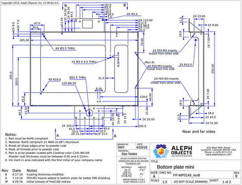
Sample Fabrication Drawing from FreeCAD
Howto
This is also called the Drawing Dimensioning Workbench in FreeCAD
Download
- First download Drawing Dimensioning Workbench - https://github.com/hamish2014/FreeCAD_drawing_dimensioning
- One route is command line on Ubuntu - pretty foolproof.
Videos
OSE Video Script
Notes from Lulzbot
We can learn to make excellent fabrication drawings in FreeCAD from Lulzbot - see an example fabrication drawing and discussion thread with Aleph Objects, the only open source hardware manufacturer in the world that we know of who creates fabrication drawings in FreeCAD:
Hey Marcin
I got your contact info from Jeff Moe regarding freeCAD drawings, we met briefly when you came out to Aleph. I've cc'd Julie Pettit, between the 2 of us we've made pretty much all of the technical drawings in FreeCAD here at AO. We'd definitely like to help you guys out with creating 2D fab drawings, just let us know how you want to go about it. Maybe a screen recording of the whole process as a place to start?
I've attached our custom drawing templates in case you want to make a custom OSE version, you can modify it in inkscape pretty easily to change logos, tolerance blocks, etc.
Cheers -Bam
-- Brent Mackenzie Mechanical Engineer Research & Development Aleph Objects, Inc. (970) 377-1111 x618
Non-confidentiality Disclaimer: Aleph Objects, Inc. works openly. All conversations in this email are intended to be transparent and subject to sharing, with due respect. Aleph Objects does not sign NDAs in order to promote collaboration. All of our work is free software and open source hardware. If you are discussing potential development collaboration, your work must also be open source pursuant to the Open Source Hardware Association definition.
Please see the video on our devel server located here (http://devel.lulzbot.com/mini/Gladiola/production_parts/machined_parts/videos/sheet_metal_drawing.mp4). It's one of our basic sheet metal pieces for the mini but has most of the processes that we use for other machines components. I've set up an isometric view on the 2nd page showing how to change the viewing angle on specific views, right now this seems to be the best way to do projections that show different angles in FreeCAD. My audio recording doesn't seem to be working in the recording, if that'd be helpful I can try to fix that or record on a different machine.
Title, scale and the other part specific bits of the title block are entered in FreeCAD, and the workflow is identical if you want to use the default FreeCAD template. We just created our own template so that we could have AO branding and our own tolerance block in the template. I'm working with Ben Malouf (our creative director) on getting a tutorial on creating a custom template (for fabrication drawings), I'm not sure what exactly went into that.
