Open Source Battery Pack
WARNINGS
High-ampage and high-voltage battery packs are inherently dangerous. You take absolute and full responsibility for all decisions, actions or lack of actions when messing about with DC electricity.
BMS redirect
note: this page is a full battery pack however Open Source BMS redirects to this page. there is a schematic for the JW3317 below from its datasheet which can be recreated, it is not difficult, or the nseidle circuit can be adapted (resized).
Concept

Existing Open Source Designs
- Potentially the Cordless Alliance Systems
- A Thingiverse Page by User "Solipsfilm" Titled "DIY 15Ah battery (Parkside)"
- Modifies an existing battery by "Parkside"
- Piles of Videos along the lines of DIY Powerwall / DIY Battery Bank
- I'll need to document that later
OSE Work
Source Code
GPLv3+ Licensed
very basic starting instructions:
- install git, python2, and openscad.
- git clone http://lkcl.net/bms_3dcase/.git
- run "python bms_model.py" to generate the model(s)
- run "openscad bms_model.scad" to pull up a 3D view.
Note: if modifying bms_model.py there is no need to quit openscad: it auto-detects scad file changes and will reload.
If simply wishing to download STL files, they are here: http://lkcl.net/bms_3dcase/scad/stl/
TODO (lkcl): get bms_model.py to generate BOM
3D printing the casework
This design requires "underhang" (underside support) as there are some areas which are "in air". The main box is best 3D printed "flat" (not upright). A 0.4mm nozzle (or less if desired) is recommended. 100% infill is not a hard requirement. Standard PLA is not entirely recommended given that the cells will get warm under load and charge: if they approach 60C (the glass point of PLA) the packs may begin to warp, which would be bad. PETG or better PolyCarbonate is recommended.
BOM
preliminary, will be autogenerated by bms_model.py
- 3D printed parts of case preferably done with a 0.4mm (less is fine) nozzle
- appx 30 cm of 12 guage (25 Amp) wire (black and red)
- appx 40 cm of thinner (2? Amp) wire (white)
- QTY 21 M1.5 x 6mm self tapping screws (5mm absolute bare minimum, no greater than 8mm) https://www.ebay.co.uk/itm/100-pcs-M1-5-M2-304-Stainless-Steel-sink-head-Countersunk-Head-Self-Tap-Screw-KA-/281513859657
- QTY 2 M3 x 12mm bolts, hex nuts plus locking washers. these are to hold busbars
- JW3317 BMS PCB https://www.aliexpress.com/item/4000052402113.html there are several sources for this
- various pieces of 1.5mm thick "busbar" which can easily be cut to size using tinsnips or a sheet metal cutter. two of them must have M3 holes drilled through them
- poron foam (packing foam!) behind one end of the "busbar" pieces, to act as springs maintaining contact with the cells.
- (optional) Busbars TBD dimensions, length is determined by how many packs are to be connected in parallel.
- (optional) Fork spade wire connectors, U-type, 25 Amp, for 10-12 guage wire. Alternative to busbars: requires "octopus" of connectors to get more amps (parallel connections).
Videos
http://img.youtube.com/vi/DFGCo3QW3Dc/default.jpg
Uses
- Power tools
- 3G/4G/LTE/WIFI portable routers with a much longer battery life (PCB can just about fit *inside* the pack itself)
- Vehicles
Design Advantages
- Each cell is individually monitored with its own BMS management, which significantly reduces cell damage
- An individual per-cell BMS also includes short-circuit provision and a current limiter, but without the need for extremely high-current circuits to do so
- Each cell is replaceable without soldering.
- There is space at the end of the pack to put BT/BLE, Micro-Arduino-style Embedded Controllers, GSM/3G/4G/LTE and WIFI etc. A sparkfun ESP32 for example https://www.sparkfun.com/products/13907
- Packs can be connected together with Bus Bars and interlock in a "hexagonal" space-saving arrangement without additional screws other than those necessary to connect the Bus Bars.
- The Bus Bars are external and consequently if extremely high current is required, larger Bus Bars may easily be used.
Design Issues
- Assembly currently requires a minimum of QTY 16 2.5 mm self-tapping screws.
- The Bus Bars are fully exposed and will require a cover (safety-conscious users may screw in covered wired cables with XT or Anderson Plugs instead).
- Skilled assembly is paramount: until it is screwed together there's high enough current to melt things, and enough voltage to give a shock.
JW3317 BMS schematic

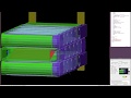
Casework preliminary screenshots


Description
Based on existing open (non-libre) designs, this is a 5-cell (18650) 18v battery holder similar to a "AA" battery holder, designed to connect safely and easily with bus-bars into larger high-ampage packs, where every single cell is individually protected from charging and discharging damage and over-current or short-circuiting. They are also designed to stack together where the cells are hexagonally overlapping, saving some space.
As a battery "holder" as opposed to a "monolithic pack", individual cells may be bought and shipped under a different category of UN3481 that may not necessarily require a Dangerous Goods Certificate and fees. Also, as a "saleable product" the cells themselves become the end-user's responsibility.
The recommended BMS for the "really simple" version uses the China-made JW3317 https://www.aliexpress.com/item/4000052402113.html where the absolute-minimal schematic and "datasheet" is available here: https://www.joulwatt.com/en/proinfo_3488.html
The actual cells are visible from both the top and bottom. This has the side-effect of making it easy to assemble, inserting tight-fitting Bus-Bars into the 3D-printed plastic. Internal nickel-copper-plated Bus-bars backed with poron foam as an easy-to-construct spring create a high-ampage contact between cells, where the BMS wires may easily be soldered to each Bus-Bar rather than to the 18650 cells themselves (causing damage and inability to replace the cells). At one end the internal bus-bars slot firmly into the lid, where at the other end they are embedded into the plastic with poron foam behind them.
The BMS circuit sits at an angle inside the 3D-printed pack, to save space. The battery wires (12 guage, 25A) connect to large upright metal squares that have a screw-hole through the middle. These squares are embedded firmly into the 3D printed plastic. From the top, through a hole that goes right the way through the pack, small enough to not permit fingers to get into, *external* Bus-Bars with over-sized holes in them are "dropped" then, on proper alignment, screws inserted that lock the external Bus-Bars into place.
The external Bus-Bars also therefore act as a mechanical means of holding multiple packs together. To save space, rather than have extra screw-holes at the other end, the packs can be slotted together (interleaved) with a hexagonal cell-overlap, such that if four or more packs are assembled together, the external Bus-Bars at each end help clamp and support the entire block. With the hexagonal overlap and the screws holding every pack onto two Bus-Bars there is simply no way to pull the packs apart.
Initial versions of this concept (right of diagram, square-looking drawings) were self-enclosed. They also required a metal plate at the end to "clamp" multiple packs together. On the left-middle is the hexagonal-interleaved design concept.
For the BMS the much-preferred option is the BQ76920 IC which has full I2C control and monitoring, suitable for integration with Embedded Controllers. Unlike the Grin Tech LiGo packs, which run proprietary firmware on an unidentified EC, an arduino-like ESP32 which has integrated BLE 4.0 and 2.4ghz WIFI, is greatly preferred. nseidle's Eagle-based sparkfun PCB is a good starting point https://github.com/nseidle/BMS
However for an initial release, the off-the-shelf and ridiculously dirt-cheap JW3317-based PCB is a pretty good start.
Questions
feel free to put questions for clarification here: put four tildes in at the end to get a name and date timestamp
- Does the cheapo form factor controller fit as is into the case? Marcin (talk) 14:50, 19 January 2020 (UTC)
- What is the advantage of a 5s over a 6s pack? Marcin (talk) 14:50, 19 January 2020 (UTC)
Notes
On 12/31/19, Marcin Jakubowski <marcin@opensourceecology.org> wrote: > Wow, that's great insight here. Can we get our hands on the Grade A cells,
if you have connections in the automotive industry, or want to place a multi-tens-of-millions of dollars cash order... yeah.
> or do we just work with shit cells now?
work with shit cells - everyone else does. for power tools they don't give a damn, just stuff them into a pack with a sub-standard BMS, the cells are so badly stressed they're toast within 250 charges anyway.
if you want to make them last longer you pay a bit more for a half-decent BMS (google nseidle github BMS BQ76940), but what you also do is charge and discharge all the cells, then mix/match them with other cells of equal internal resistance and other characteristics.
there's actually a libre-licensed USB "cell tester" online, somewhere. full schematics, full source.
> Please do share what you have on the battery pack design. For the workshop > - we wanted to do 6s (22v), and stack them for the welder application for > minimall a 5 stack and 50A for 3/32 welding rods.
for what we are doing (EVs) we need to go with 18v (5 cells) because it's nice multiples: 36v, 72v are easy well-known numbers.
> We were going to get this BMS off-shelf - > https://www.banggood.com/10pcs-6S-14A-22_2V-18650-Battery-Protection-Board-for-18650-Li-ion-Lithium-Battery-Cell-Charger-Protect-Module-PCB-BMS-p-1542693.html?rmmds=buy&cur_warehouse=CN
aw bless 'em. it's really basic, and funnily enough i was looking for something pretty much exactly like this. they even used a china-clone rip-off of the Fairchild Semi FDD8447L MOSFET. awww bleeesss :)
here's the (very basic) datasheet which includes the schematic. absolutely no information on how to use it, no information on how to set the max current etc. etc.
https://www.joulwatt.com/en/proinfo_3488.html
oh btw, at $35 you're being ripped off. a quick search "JW3317 site:aliexpress.com" came up with this: https://www.aliexpress.com/item/4000052402113.html
which is USD $2.53 with free shipping to the US, and it's clearly exactly the same circuit.
> - > would that work?
it'd work. what you can do btw is still use that, with only 5 cells. connect (short) any one cell to two of those pads (B3 and B4), that should tell the JM3317 "hey one of my cells must be dead, that's ok, let's just skip that one and carry on anyway"
> Doesn't look like the TI BQ76940, though.
the BQ769x0 series has the advantage of being fully-documented. as in: *everything*. it also has an I2C interface, i.e. you get full control, monitoring and reporting, from an Embedded Controller. it also has the advantage of being part of nseidle's Eagle-based BMS.
however for "getting started", the JM3317 one is pretty f****** good, and i'm going to recommend it to my business associates to get some and try it out.
(we have to do a pack demo of the concept i sent you, including charging them).
BOM
- 6s 18650 charge controller - [1]