Tom Log
Tom Griffing's Log

Fri Feb 20, 2026
Took frames from yesterday's work and some others that were in the Learning Center and built the last full modules. Marcin asked that we also add diagonal compression supports on the end to prevent it from sagging. Installed the last roof section to the hangar. Yay!
8 hours.
Thu Feb 19, 2026
Worked with Collin to build short frames for building the last roof module, then continued with Roy to re-build the roof module jig for the short roof modules. It only had three of the frames instead of the usual five frame as on the full roof modules.
8 hours.
Wed Feb 18, 2026
Worked with Roy to build modules for roof sections. Before lunch, Collin arrived and Marcin asked that I work with him in the workshop to build "short" 16' frames for hangar modules. Built 8 of them before being re-directed to build two 11" wall headers: 7' 2" and 12". Spent the rest of the day working on them.
8 hours.
Tue Feb 17, 2026
Worked with Roy to build modules for roof sections. Helped Jeremy attach modules together to build roof sections, used Kioti to move modules to end of hangar. After the others had left, used the Kioti to grade the path from Willow to the end of the hangar, as it was very rough.
During lunch, reset password for Catarina to access the Wordpress admin page. Later, I received an email from her saying she couldn't add new themes, so researched it and enabled her to add themes.
8 hours.
Mon Feb 16, 2026
Work on roof modules, with Roy and Jeremy. Helped Marcin connect the dump trailer to the truck, then stopped for lunch. Catarina mentioned that she wasn't able to log into Wordpress admin dashboard, so reset her passwords for two accounts. Continued work on roof modules.
Sun Feb 15, 2026
Spent 1.5 hours tweaking wp-dev, getting access to the local admin dashboard and verifying credentials for Catarina and Marcin.
Went to Hablab and visited with Roy and Jeremy, talking about all manner of things, including some gripes about things OSE.
Returned to the house and relayed the gripes to Marcin.
Spent the balance of the day in the Hablab, cooking a dinner for us all and "hanging out" with the guys.
Sat Feb 14, 2026
Day off from Hangar construction. Spent most of the day working on wp-dev ose Wordpress site, back and forth with ChatGPT, trying to fix the website. The "Enigmatic" theme on the site was causing all manner of problems, throwing exceptions and ChatGPT kept suggesting to fix code in the theme. I found a problem in one file, asked ChatGPT what to do about it, changed some code to fix the issue, restart the server, then a problem would appear elsewhere in the same theme.
After hours of this, I queried about upgrading the theme. The answer was yes, but it is a paid theme and Catarina had said before that she wanted to change to a different theme - so I queried about changing themes. After downloading and changing themes, the system quit working and ChatGPT said the wordpress core should be upgraded, but when trying this, the upgrade failed due to the new theme in place.
Since this instance of Wordpress had been a migration from Hetzner2, I deleted it from Hetzner3 and fetched a fresh copy from the other server. I started with a new Wordpress installation, overlaid it with the content and database from Hetzner2, did some updates and the system was mostly working. 4 hours.
I spent a few hours with Roy and Jeremy, taking them to "The Old Cookstove" to Walmart (Jeremy needed some things), then to a restaurant in Cameron for lunch.
Fri Feb 13, 2026
Met Marcin early while having breakfast and he wanted to get an early start on the roof modules. I went to the Learning Center, where I met Roy and we started making the "jigs" for the roof modules. Roy and I built several roof modules and brought them to the hangar to compliment the existing modules so we could install them today. After we delivered the last module we built, we began work assembling them into a roof section. Following that, the others climbed to the roof and began removing the old plastic and preparing it for the new heavy plastic. They dropped the old plastic and I used it to cover the completed roof module, should we have rain. I also moved a light into the dark hangar area and repaired a nail gun with a jam of nails in the exit chute. 11 hours.
Thu Feb 12, 2026
Continued work on access for Marcin for the OSE development website. Much dialog with ChatGPT and did rebuild nginx_proxy as suggested yesterday and also making changes to nginx and wp-dev site. While doing that, the wiki went offline due to certificate expiration. I spent time getting it working again, as it was trying to use the cert from "learn" for the wiki and wp-dev. Finally got that corrected and the wiki came online, with the Time Log working again. 3 hours.
Worked alone in Learning Center to build roof modules. At the end of the day, Jeremy and Roy stopped by and we discussed building "jigs" to speed up module construction and do so more uniformly. We will build the jigs tomorrow morning. 5 hours.
Wed Feb 11, 2026
Marcin asked for logins for himself and Catarina to the ose_wp wordpress instance. Worked in the morning to make it accessible. No easy fix yet. Continued working on it after the hangar work, still no resolution. 1.5 hours.
Worked with Jeremy and Roy to secure the NE corner walls of the hangar. Following that, Marcin asked me to work with two Mormon boys to build roof modules. We built them and moved them to the East end of the hangar for installation. Asked Marcin for diesel fuel for the telehandler and added some fuel additive. 8 hours.
Marcin requesting access to hetzner3 wordpress ose_wp. I thought it was working some time ago, but it isn't currently accessible. I've been asking ChatGPT about it and getting lots of recommendations for changing the server, but the site is still not accessible. Added new domain for the site: wp-dev.opensourceecology.org, updated the docker-compose.yml for the changes, added a new record in Cloudflare for the new site, updated nginx config and file permissions to allow "dadm" user to write to the config files.
Now, it suggests completely rebuilding nginx_proxy. I expressed reservations and will perform a snapshot of the current docker image as follows:
 Snapshot the running nginx container config

 Export the current container filesystem (this preserves everything as-is):

 docker commit nginx_proxy nginx_proxy_backup_image


 Confirm:

 docker images | grep nginx_proxy_backup_image

 This gives you a frozen image of the exact working state.

 Save current mounted nginx config (important)

 Since you bind-mounted /etc/nginx/conf.d, copy it:

 sudo cp -a /etc/nginx/conf.d /etc/nginx/conf.d.backup-$(date +%F)

 Also save certs just in case:

 sudo cp -a /etc/nginx/certs /etc/nginx/certs.backup-$(date +%F)
After rebuilding nginx_proxy, the websites weren't working, so I changed docker-compose.yml and uncommented the line:
- /etc/nginx/conf.d:/etc/nginx/conf.d:ro ## Removed per ChatGPT TLG 2-11-2026
Then rebuilt the nginx_proxy container:
$ docker compose up -d --force-recreate nginx_proxy
and the website worked again.
Tue Feb 10, 2026
Worked with Roy and Jeremy to secure the hangar section installed yesterday and on assembling the final corner section, got it mostly ready to hoist. Also worked on correcting the South/East corner section, as the door width was wider at the top than bottom. Later, drove to Menard's for more screws for tomorrow's addition of 3 new helpers to work on completing the roof sections. 10 hrs.
Mon Feb 9, 2026
Worked with Roy and Jeremy to remove wall modules from the provisional hangar doors, then assemble them into hangar wall sections and attach to the hangar. We assembled them on the ground and when ready, used the telehandler to lift them into place and secure with fasteners. 10 hrs
Sun Feb 8, 2026
Drove to OSE, arrived around 3:30 PM. Unpacked into the room by Marcin's house. Surveyed the hangar, hablab, etc to get an idea of the status of the place. Roy arrived adn we cleaned up the hablab while Roy settled in. Went with Marcin to get an idea of the work to be done: Continue building hangar - wall modules are complete and ready to put up, using the telehandler.
We checked the air compressor and it needs oil. Later, checked its documentation and its oil should be changed right away (supposed to change after 8 hours of operation). Also: Check the belt tension and add an electrical "On/Off" switch.
Sat Jan 24, 2026
Marcin sent email about bot activity impacting server performance. I did see bots, wrote the "showbots" script (run as dadm user). I also created a conf file to deny bots by IP address "/etc/nginx/conf.d/blocked_ips.conf. Also sent Marcin summary.
Thu Jan 8, 2026
Got up early and worked on the server, along with ChatGPT. Found problems with healthcheck blocking I/O and fixed it.
Also fixed the problem with the Time Log not appearing - turned out to be due to the authentication between osedev and pdb processes. Resolved it and the Time Log resumed working.
The wiki pages are still having pauses when rendering pages. With more diagnosis, I found that the "opcache" was not enabled in mediawiki. After enabling it, the performance seems better.
Wed Jan 7, 2026
Call from Marcin about Hetzner3. Walked him through getting logged into his own account via SSH with certificate and enabled him to log in using the "dadm" account for Docker administration. Checked the server status and found high load averages. Rebooted the server, performance did not improve immediately, but it did over the next few hours. Stopped and agreed to resume later.
Here is the chat link: ChatGPT_link
Sun Dec 14, 2025
Connected heat pump module and ran it, warming the room.
Worked with the attendees to pick up trash and burn in burn pile.
Late meeting in Hablab - got out after 9:30.
Sat Dec 13, 2025
Drove to Menard's for sheet rock, etc.
Worked on second Heat Pump module - got it mostly completed.
Fri Dec 5, 2025
8:00 meeting in Hablab. Completed Hangar utilities: Compressed air, ethernet WiFi and electricity to all 6 production bays. Reviewed the installation and updated some clips for compressed air lines to prevent condensate water from pooling.
Following that, Marcin asked to trench for a water line from the municipal water source to the Hangar, completed and retired for the day.
Thu Dec 11, 2025
Link to Hangar water supply design document: https://docs.google.com/presentation/d/1DkW8vWvtUWWCLe7rb1LnvKB-DyR8jWQ9DOva3jfAie8/edit?slide=id.g3ae1e878243_0_0&pli=1#slide=id.g3ae1e878243_0_0
Note: It will be changing in the next few minutes
Wed Dec 3, 2025
Drove to Menard's for yet another load of lumber. Ethernet progress: got Nick and Joe to work on terminating the wire from the hangar to the workshop. They were having trouble crimping connectors properly. Completed all but one bay's compressed air connections. Got Brandon working on loading OSE Linux 3.0 onto the Intel NUCs. Also requested installing the old version of Freecad (version 0.16) and adding a desktop GUI launcher to run the LD_PRELOAD command in the same command string as for launching the Freecad 16 appimage.
Tue Dec 2, 2025
8:00 meeting @ Hablab. Left early to bring Catarina's sink to the house. Got Roy to help.
Continued work on compressed air delivery. Found that the filter/regulator does have 1/2 inlet, but only a 1/4 regulator output. Found fittings to connect PEX to compressor - one 1/2" coupling was plastic and had a split along one side, leaking air. Discussed with Marcin and made a run to Sutherland's for connectors - they only had 3 sets, so purchased them, returned and connected 3 bays.
Mon Dec 1, 2025
Work on Hanger utilities. 9:00 meeting @ Hablab. Returned to Hanger, worked on air and electrical outlets. Break for lunch @ hablab. Had quick dinner, then made run to Menard's for partial load of lunber, as the roads were icy.
Sun Nov 30, 2025
8:45 meeting @ Hablab. Asked Mark to help with installation of electricity in hanger bays.
Collected supplies and connected 4 bays and compressor with electricity.
Sat Nov 29, 2025
Still composing and refining the lists for purchasing. Reached an end and sent to Marcin for final review / update.
Drove to Saint Jo Menard's to pickup the items from Harbor Freight, Home Depot and Menard's and fetched the items.
Collected computers, intending to reload them, but crashed to sleep instead.
Fri Nov 28, 2025
8:00 meeting in Hablab.
Drove to James' house and got the 5 computers for the workshop. Spent the balance of the day working on lists of items necessary for installing compressed air, electricity and networking in the hanger.
6:00 meeting in Hablab.
Back to the house to continue the lists and get input from Marcin.
Thu Nov 27, 2025
Attended 8:00 AM meeting @ Hablab.
Used Kubota & grader to level out the ground from all the clumps of clay. Dug hole for final run inside the hanger. Made long 3" spade drill and used it to make the hole - with Roy's help. The poly tube kinked again inside the hole. Fixed Roy's reciprocating saw. In the house, discussed finding a coupling and repairing the poly line below ground.
Marcin found pellets for the pellet stove and I fetched a bag for the house.
Wed Nov 26, 2025
Attended 7:45 meeting @ Hablab.
Asked Aiden to help laying wire and blue CTS tubing in the trench. The tubing was not flexible and "pinched" in several places. Discussed it with Marcin and used pieces of the CTS tube with hose clamps to repair the pinches One pinch was left in the ground, near the exit into the hanger - it will have to be fixed, but the decision was made to move the compressor to the hanger and connect locally. Also ran ethernet cable from the workshop to the hanger and buried the trench.
Late night run to Menard's in KSC to pick up insulation.
Tue Nov 25, 2025
Took the hose and drove to Sweiger Shop, where they repaired it for ~ $40. Returned to OSE, installed hose and ran trencher to continue trenching. Trouble with trench filling in from others and from my own efforts to lay the wire and tubing in the trench. The wire proved difficult to handle, as it is heavy and when straddling the trench backwards, the wheels of the skid steer got stuck. Marcin used telehandler to get it free.
Made late night run in truck/trailer to Menard's for more insulation.
Mon Nov 24, 2025
Drove truck/trailer to Menards, loaded OSB and 2x6's and returned to OSE. Connected trencher to Kubota skid steer and dug trench from Workshop to Learning Center. While running the trencher, one of the hydraulic hoses was "pinched" and had to be repaired to continue. Spent hours searching for a solution - none found. Got Aiden to help.Late night run to Menard's with truck/trailer for insulation. Only 1/2 of the order fit in the trailer.
Sun Nov 23, 2025
Arrive at OSE at 2:00 PM. Discussed needs with Marcin, started working on the Kioti skid steer: Change oil, clean filter and oil/water coolers, straightened safety bar. Drove truck/trailer to Menard's for supplies, but it was closed (Sunday).
Sun Nov 16, 2025
Email to Marcin/Catarina about coming up for the 1 week work exchange and workshop. All good to go. I'll arrive Sunday the 23rd (the day after the work exchange starts), resolved with Marcin. Began gathering tools for departure on Sunday the 23rd.
Fri Nov 7, 2025
Marcin called: take a look - when I click on these files - I get an error. The last one is a re-uploaded version which works.
https://wiki.opensourceecology.org/wiki/Hangar_3D_CAD
More testing showed that clicking on the "Date/Time" of the current version yields a "Not Found" page.
I ran it down and found the files were missing from the "images" folder. I got a copy of the "images" folder from Hetzner2 and did an extract, keeping all existing files and copying missing files to the "images" folder.
All 4 files are available now.
The files that were missing had dates of June 21 or so and may have been added while the server was being migrated.
Mon Oct 20, 2025
Marcin called at 5:23 AM, saying the redirect quit working. Troubleshooting with ChatGPT resulted in working on various things, but with no solution. It led me through troubleshooting of nginx, wordpress, varnish, DNS, server name ordering and other criteria. Each time, it stated it found the solution, but following each update, it failed to perform the redirect. At one point, it said the issue was with the cloud version of Varnish, which required a login to administer. I searched, but did not find credentials for the cloud version. Instead, I requested to bypass varnish entirely and tested it, but the result was inconclusive.
Finally, I called Marcin and told him of the diagnostic loops that I've experienced with AIs in the past and he said he'd have the video updated with the information so the redirect would be unnecessary.
Sun Oct 19, 2025
Continued on the redirect of the main page of opensourceecology.org, but not the subpages (per Marcin). Queried ChatGPT and did some checks to find that nginx was still doing the redirects and not apache. Changed the nginx config, restarted nginx and now it works. Verified that Marcin saw the result.
After seeing Marcin's message about a site outage, I did some digging and found a problem with database connections failing, due to the default limit of 50 connections. I added a startup config file (nano /etc/mysql/mariadb.conf.d/99-custom.cnf) to inclulde the following:
 [mysqld]
 # Increase connection limit to handle multiple apps
 max_connections = 300

 # Optional: shorten connection timeout to free stuck sessions faster
 wait_timeout = 180
 interactive_timeout = 180
and restarted the server. I monitored the connections and saw that it is regularly exceeding 100 to 115 connections - which was likely throwing connection errors regularly.
Sat Oct 18, 2025
Marcin called with the need to do some web redirects to streamline content for new applicants. Consulted ChatGPT and made the suggested changes. Marcin called after a short time, saying it isn't redirecting as expected, so I restored the original config. Later, did some more Chatting and changes, but used "curl" to better diagnose the situation and found that redirects were happening in nginx that blocked the apache redirects. Marcin said to put back to the original config and start fresh tomorrow.
Thu Oct 9, 2025
Noticed that the "www.opensourceecology.org" page is yielding a certificate error. Worked with ChatGPT, but no resolution yet. Will continue tomorrow.
Wed Sep 17, 2025
Marcin sent email, reporting that error messages were appearing from the ConfirmAccount extension:
Deprecated: strlen(): Passing null to parameter #1 ($string) of type string is deprecated in /var/www/html/extensions/ConfirmAccount/includes/backend/UserAccountRequest.php on line 51
The error was coming from the following code:
$req->fileName = strlen( $row->acr_filename )
   ? $row->acr_filename
   : null;
The call to strlen passes a null filename, causing the exception, so the fix was to change it as follows:
 Original: strlen( $row->acr_filename )
 Changed:  strlen( $row->acr_filename ??  )
This passes an empty string to "strlen()" rather than a null, suppressing the error.
Fri Sep 5, 2025
Marcin email: User having trouble. Send screenshot and copy Tom.
I received the error and tracked it down to a config error - fixed it in LocalSettings.php, tested and verified working now. Sent user update.
Sat Aug 30, 2025
Marcin issue with Time Log. He now says he was only able to access it from his computer using the Firefox browser, but can now access it using Chromium - so it's OK on his computer.
His phone still can't display the Time Log, though. It fails with the message "osedev.org redirected you too many times".
Fri Aug 29, 2025
I came across a company in Australia casting Lego like blocks of perlite for building houses:
I just came across a video about these blocks for building walls with LEGO like blocks:
https://www.youtube.com/shorts/1EWpcrFTYHo
I had seen some in the past, but these look more interesting.
Apparently, it is from the Australian company "System3E":
https://system3e.com.au/
They claim:
Made of perlite (recyclable)
LOW TOXIC HOME – natural materials, safer for your family
THERMALLY INSULATED – 10x better than the standard Australian house brick
MOULD RESISTANT – perfect for humid regions of Australia
   FIRE-RATED 240/240/240 – resistance to temperatures from 200°C to 900°C
   → no mortar → no water → no glue
   → no additional insulation
   → no freedom of movement in any dimension
While the block design looks good and I like perlite, I don't know its cost, availability or suitability for a building material.
- - - - -
Yesterday, I came across a video of a guy making blocks out of "AIRcrete":
https://bastyon.com/index?v=7fbdf470f514561b3aad7351dfea2c10c12317e8fb2148b2c6327f94e66cccd7&video=1&ref=P8s7mXn1msepNnpCp3FyoxXoGzxNSWHxxz
I was interested, did more searching and found some info about AIRcrete:
This article claims that AIRcrete gets R-6 / inch:
https://www.buildwithrise.com/stories/aircrete-everything-you-need-to-know
I also found a website about "Aircrete Europe" that already builds with blocks and panels:

- - - - -
Following that, I found information about HEMPcrete (also called "hemp-lime") which has passed European and US standards for use as insulation and had been measured with R-value of 2.2 / inch:
https://www.hempbuildmag.com/home/hemp-lime-astm-r-value
It goes on to say that HEMPcrete has "thermal inertia", which benefits heat propagation.
Homeland Hempcrete makes prefab hempcrete wall panels that look familiar:
https://porpoise-jaguar-g36w.squarespace.com/

Fri Aug 22, 2025
Email from Marcin saying he was blocked when trying to create an account with the URL:
https://wiki.opensourceecology.org/wiki/Special:RequestAccount
I tried this from my login and it worked normally, with a form to complete for the account request.
When looking at the mediawiki logs, I saw an unusual number of attempts to invoke this "Special:RequestAccount" URL - they were failing, but still showing in the logs.
Marcin called later in the day and I reviewed this with him. I also informed him that the "Time Log" was working. We visited my "Tom Log" and he could see it working, but when visiting his Log, he got something different - he will pursue this later.
Thu Aug 21, 2025
11:00 PM call from Marcin: "User account creation has been hacked". I checked it out and found 373 users created in the last 2 days - most without Marcin's approval.
Inquired about it to ChatGPT and made some changes to the LocalSettings.php file on mediawiki, with the help of ChatGPT and also queried the database and found the bogus users. Notified Marcin and will check on it tomorrow.
SQL to show users created since yesterday:
SELECT user_id, user_name, user_registration FROM user WHERE user_registration >= '2025-08-20' ORDER BY user_registration DESC;
It identifies 373 users. Marcin looked at the list and recognized some entries, so we can't just delete them all (via UserMerge).
Locked down self-registration with the following settings in mediawiki LocalSettings.php:
 # Disable normal self-registration
 $wgGroupPermissions['*']['createaccount'] = false;
 $wgGroupPermissions['user']['createaccount'] = false;

 # Allow only sysops (or bureaucrats) to create accounts manually
 $wgGroupPermissions['sysop']['createaccount'] = true;

 # ConfirmAccount will handle public requests
 wfLoadExtension( 'ConfirmAccount' );
 $wgGroupPermissions['sysop']['confirmaccount'] = true;

 $wgGroupPermissions['sysop']['confirmaccount'] = true;

 $wgConfirmAccountRequestEmail = true;   # email admins when new requests arrive
Sat Aug 16, 2025
Worked on the OBI web service in early morning - per agreed maintenance window of midnight - 9:00 AM.
Changing certificate config in nginx_letsencrypt container and regenerating certificates for nginx_proxy. It required restarts of both to make effective.
Got call from Marcin at 8:30 AM, saying website down. He must have hit it during restart of nginx_proxy, as it was up when he called. Stopping for today.
Fri Aug 15, 2025
Working on OBI Wordpress: Downgraded the container to php 7.0 and Wordpress 4.8.1.
Trouble with the domain names, nginx and SSL: Couldn't access site via https. ChatGPT suggested adding both "openbuildinginstitute.org" and "www.openbuildinginstitute.org" to the "VIRTUAL_HOST" definition of obi_wp, but this ended up breaking nginx_proxy and all sites. Scramble to get it working again and got a call from Marcin about it. Once restored, called Marcin and notified. Stopped for the day.
Thu Aug 14, 2025
Enabled users to create their own accounts and enabled ConfirmAccount extension so Marcin approves accounts before creation.
Fixed bug with strlen() due to new version PHP.
Fixed osedev Time Log reporting in mediawiki iframe.
Added osedev's postgres database dump and backup to system scripts.
Working on getting the OBI wordpress container "cloned" from H2 to H3.
This appeared to be easy, but is taking time, due to incompatibilities with wordpress, PHP, base docker images and so on.
Here is the dialog with ChatGPT: https://chatgpt.com/share/687596c4-8470-800e-8513-e7e3bbed6976
Wed Aug 13, 2025
Marcin called with priorities:
 * Enable users to create accounts on wiki
 * OSEdev integration
 * OBI: Clone from Hetzner2
Enabled user account creation with: Mediawiki -> LocalSettings.php -> $wgGroupPermissions['*']['createaccount'] = 'true';
Fri Aug 8, 2025
Video call with Lex about osedev.
I had installed the osedev apps and a postgres database in a container and we decided to split them into separate containers. Defined, built and started the "pdb" (Postgres DataBase) container and imported the data from Lex.
Setup an "osedev" container and loaded the apps using Lex's docker config information. We were able to start it and connect it to the database, but the access via https was not working. Did some work to get it connected using the domain name "osedev.opensourceecology.org", but had trouble with the nginx configuration and SSL certificates. Reviewed the current configuration and found changes needing to be done. Worked with Lex on it for some time and he is confident that the app is working, just not connecting.
He had to go, so I'll work on it and get back with him as necessary.
Note that Lex has put the code for osedev in github: https://github.com/osedev/osedev/tree/master
Thu Aug 7, 2025
Video call with Lex about osedev.
Did screen share to show the current config and we discussed the use of docker-compose to define the containers.
Lex did some coding on-screen, trying to get docker-compose to automate the pull from Github and build of the container. We worked at it for some time, then Lex ran out of time and said he would complete it and get back with me.
Tue Aug 5, 2025
Re-exported the postgres database into text dump file. Installed "pgloader" and tried it for converting the postgres file into MySQL - it failed. Un-installed it.
Fetched the perl script: pg2mysql.pl and used it to convert the postgres dump into a MySQL ".sql" file. Looked it over and found it creates and loads into the "public" database. Loaded it into my MySQL database. It largely went OK, but threw some errors over "timedate" exceptions. Notified Lex and Marcin.
Also: Sent Lex request for the GUI portion of his app.
Mon Aug 4, 2025
Got postgres database dump from Lex, created postgres v10 container on my PC and imported the database.
Wed Jul 30, 2025
Fixed the phplist site after the "build" broke it. Updated docker-compose.yml and the Dockerfile to restore the config if rebuilt again. Got the phplist functionality working.
The Dockerfile and site configurations are in "/home/dadm/OSE/phplist-3.6.16".
Also checked on the obi_wp site, as it was showing as "unhealthy". Turns out the "oshin" theme was set for the site, but was not to be found. Fetched and installed it from Hetzner2, but got an error saying it is not compatible with the updated version of wordpress. Switched it to the "twentyfive" theme and sent email to Catarina about the switch.
After all this the sites all show as "healthy" and are accessible from the Internet.
Catarina sent email with attachments of receipt and the oshine theme. I installed it and after some testing, the site appears to work, but with little content. I requested that Catarina check it out and let me know if working properly.
Notes:
Wordpress version 6.8.1 is currently installed in the docker containers. PHP is at version 8.2.29
ChatGPT had a few things to say about this theme and Wordpress versions and the oshine theme:
The theme is loading translations before the WordPress init hook, which is not allowed anymore as of WordPress 6.7.
“Optional parameter declared before required parameter” - This is caused by PHP 8+ strict rules. The theme uses outdated PHP 7-style function signatures.
 Attempt to modify property "admin_notices" on null
 This means the Redux global object the theme expects wasn't initialized properly — likely due to changes in the WP core or incompatible plugin code.
Final Notes
WordPress 6.7 tightened the rules for translation loading timing.
Oshin (or at least its bundled libs) hasn’t caught up.
Best practice is to hook all load_theme_textdomain() calls into init — but older themes often don’t.
With these considerations, it may be best to use a different theme.
Tue Jul 29, 2025
Continuing with mail setup: Added new container "mail-relay" to handle outbound email for all containers. Added this block added to docker-compose.yml, then ran "docker-compose up -d" to create the container:
   mail-relay:
     image: boky/postfix
     container_name: mail-relay
     hostname: mailer.opensourceecology.org
     restart: unless-stopped
     environment:
       # Change these to match your actual SMTP relay credentials
       RELAYHOST: ""
 #      RELAYHOST_USERNAME: "postmaster@yourdomain.com"
 #      RELAYHOST_PASSWORD: "your-password"
       MYHOSTNAME: "mailer.opensourceecology.org"
       SENDER_CANONICAL_MAP: "phplist@opensourceecology.org"
       ALLOW_EMPTY_SENDER_DOMAINS: "true"
     networks:
       - ose-net
I tested different package configurations, settled on using only exim4 in each container to forward email to mail-relay as follows:
As "dadm", start a shell in each container to install the packages and create the initial config:
 dadm@hetzner3:~/OSE$ docker exec -it wiki bash
 # apt update && apt install -y vim-tiny exim4 bsd-mailx
 # vi /etc/exim4/update-exim4.conf.conf # Add the following, changing "wiki" to the container name:
 dc_eximconfig_configtype='smarthost'
 dc_other_hostnames='wiki.opensourceecology.org'
 dc_local_interfaces='127.0.0.1 ; ::1'
 dc_readhost='wiki.opensourceecology.org'
 dc_relay_domains=
 dc_minimaldns='false'
 dc_smarthost='mail-relay:25'
 CFILEMODE='644'
 dc_use_split_config='false'
 dc_hide_mailname='true'
 dc_mailname_in_oh='true'
Run these commands to update the config and restart the mail service:
 # update-exim4.conf
 # service exim4 restart
Test for email sending and delivery to my email client:
# echo "Test from ose_wp" | mail -v -s "Test Email" tgriff@tuta.io
I set up this mail service for the following containers:
 wiki
 ose_wp
 obi_wp
 learn
 phplist
Received an email from Lex, saying osedev.org was broken and offering to assist with migrating the timekeeping app to Hetzner3. It uses postgresql and I have concerns that it may be rather "heavy" for adding to Hetzner3.
Mon Jul 28, 2025
Per Marcin's request, turned on user self-registration by adding the following to Mediawiki's "LocalSettings.php" file:
 wfLoadExtension( 'ConfirmEdit/ConfirmEdit.php' );
 wfLoadExtension( 'ConfirmEdit/ReCaptchaNoCaptcha' );

 $wgCaptchaClass = 'ReCaptchaNoCaptcha';

 $wgReCaptchaSiteKey = 'your-site-key-here';
 $wgReCaptchaSecretKey = 'your-secret-key-here';

 // Optional: Enable CAPTCHA for self-registration
 $wgGroupPermissions['*']['createaccount'] = true;
 $wgCaptchaTriggers['createaccount'] = true;
I accessed the Google reCaptcha website to generate the keys for it to work. While there, it asked which type reCaptcha to use and I selected "Score based (v3)", which uses a score and is invisible to the user.
After installing the keys, I visited my OSE wiki page for logs and found the iFrame with user hours and graph had been replaced by an error message about a certificate issue with "osedev.org". Since I don't know this server, I sent Marcin an inquiry about it and am waiting for his response.
Also configured the following:
 ConfirmEdit - Prevent bot submission
 email verification - Block junk account editing
 StopForumSpam - Check against known spammers
 wgAccountCreationTrottle Limit account creation to 1 per IP addr per day
 AbuseFilter - Detect sketchy usernames, etc.
 ConfirmAccount - Manual review of signups
Started configuring and found the hourly tracking feature not working on personal log pages. Looked into it and found the iFrame content was blocked from osedev.org (Lex's machine). Later, had to disable several of the options as the wiki server wasn't rendering pages.
Configured limits on log files in the docker-config.yml.
Sat Jul 26, 2025
Monitoring backups, checking into automating monitoring for the rsyslog events. Marcin email: Enable "Create user" function from main page? I looked and found a way to enable it in the sidebar menu only for administrators.
Thu Jul 24, 2025
Reviewing the security of the newly installed Hetzner3, I used "nmap" to test each port for accessibility:
 $ nmap 144.76.164.201

 Starting Nmap 6.40 ( http://nmap.org ) at 2025-07-24 07:20 UTC
 Nmap scan report for hetzner3 (144.76.164.201)
 Host is up (0.00032s latency).
 Not shown: 998 closed ports
 PORT    STATE SERVICE
 80/tcp  open  http
 443/tcp open  https

 Nmap done: 1 IP address (1 host up) scanned in 0.03 seconds
This is good, as only two "priviliged" web server ports are exposed to the Internet.
The web services provided by Hetzner3 are "front-ended" by nginx configured as a "reverse proxy" to secure the back-end server processes. In a query with ChatGPT about the benefits of using this configuration follow:
Me: Describe how using nginx to provide "reverse proxy" interface to web servers enhances security.
ChatGPT:
Using Nginx as a reverse proxy enhances security for your web servers in several key ways. Here’s how: 🔒 1. Isolation of Backend Services
Direct access to backend servers is blocked.
Clients only communicate with Nginx, not the actual web servers (like Apache, PHP apps, Node.js, etc.).
This reduces exposure to vulnerabilities in those backend services.
🔑 2. SSL Termination
Nginx can handle TLS (HTTPS), even if backend services only support HTTP.
It centralizes certificate management and:
Ensures secure connections with clients.
Prevents misconfigured backend HTTPS.
🧱 3. Rate Limiting and Throttling
Nginx can apply rate limits per IP, defending against:
Brute-force login attempts.
API abuse.
DDoS attacks (to some extent).
🚫 4. Access Control and IP Whitelisting
Nginx can restrict access to certain routes, IPs, or headers before traffic reaches your application.
Example:
location /admin {
 allow 192.168.1.0/24;
 deny all;
}
🧼 5. Input Sanitization & Filtering
Nginx can block common attacks like:
SQL injection attempts.
Malformed requests.
Unexpected methods (TRACE, TRACK).
Tools like ModSecurity or ngx_http_limit_req_module enhance this further. 🎭 6. Obscuring Backend Details
Headers like X-Powered-By: PHP/7.4 can be removed.
Backend IPs and server software versions are hidden.
Makes fingerprinting your infrastructure harder.
🕵️ 7. WAF Integration
Nginx can be used with a Web Application Firewall (e.g., ModSecurity or NAXSI) to inspect traffic for malicious patterns.
📜 8. Centralized Logging and Monitoring
Logs from all services pass through Nginx.
Easier to detect anomalies, attacks, or unusual patterns in one place.
🧩 9. Buffering and Request Validation
Nginx buffers client requests and can reject oversized payloads or invalid content types.
This protects slower or less robust backends from being overwhelmed.
🛑 10. Preventing Open Redirects & Proxy Abuse
Nginx can tightly control which headers and URLs are passed to the backend, blocking:
Open redirect vulnerabilities.
Abuse of internal-only APIs.
In addition, docker has been installed as "rootless" so if a container is compromised, any access is limited to the Docker Runtime user.
Worked on the retention script for backups. I implemented it in two parts: one for local backups and a second for remote (backblaze) backups. The schedule is to keep the following backups:
 7 Daily
 4 Weekly
 12 Monthly
 5 Annual
I used python with an API library to access Backblaze for inventory and deletion of old backups. After much testing, finally arrived at a version that works well. Tested it to success and appended it to the main backup.sh script.
Also checked the backup log file and found it lacking. Tweaked the backup script for clarity. The scheduled backup ran just as I finished. Checked the log file again. Deleted an unnecessary 4.5 GB database backup file to save space on disk and on the backup.
Wed Jul 23, 2025
Copied phplist images from H2 to H3 and installed them. Tested and found the resulting content updated with images. It appears the phplist implementation is complete.
Mon Jul 21, 2025
Resolved the issue with phplist content loading into iframes on www.opensourceecology.org - now it loads properly. It was due to the "DocumentRoot" not serving up the same directory path as the prior server.
Communicated with Marcin about a cutover of the www OSE wordpress site and phplist to the new server - will wait until the current campaign is over and we've reached a time of minimal updates.
Sun Jul 20, 2025
Continued on phplist and configured it to auto-build into the docker framework. Had a few slowdowns, mostly related to the auto-build in Docker, but got past it and the configuration went easier. Connected phplist to the database.
Sat Jul 19, 2025
Started into phplist and got into postfix for mail delivery. It appears that emails are sent directly to subscribers with no middleware. Studied the setup and started working on phplist. Found incompatibilities with it and PHP 8.1. Kept hitting stopping points that required debugging to find / fix the incompatibility.
Since I didn't know how many more of these issues would present themselves, decided to upgrade to the latest version of phplist, which is compatible. Installed phplist 3.6.16 and began configuring.
Fri Jul 18, 2025
Working on phplist server, drilling down into the processing, found and fixed some errors in scripts that were prevent it from working. Found email service needs to be configured, so set about copying the config from hetzner2.
Thu Jul 17, 2025
The phplist content from hetzner3 still isn't working. When I bring up www.opensourceecology.org from Hetzner3, everything is working except the iframe from phplist. When using phplist from Hetzner2, it works fine, but when switching phplist back to Hetzner3, the iframe is blank. I've been using ChatGPT to assist in diagnosing the cause, but still haven't found a solution.
Wed Jul 16, 2025
Monitoring Hetzner3, verifying backups working as expected and uploaded to Backblaze.
Following the migration of www.opensourceecology.org to Hetzner3, began work on the site to get it working properly, as the old installation didn't work cleanly on Wordpress 6.8.1.
ChatGPT proved very helpful with this, in getting the former "Enigmatic" theme moved from Hetzner2 copied over and modified until it worked properly on H3. The only thing not working is the iframe of the phplist content. I will resolve this after phplist is working on this server.
Worked on getting www.opensourceecology.org to display the iframe from phplist correctly, but ChatGPT keeps running in circles and changing models, making it very challenging. Stopping for today, will continue tomorrow.
Tue Jul 15, 2025
Continued with phplist to completion. Emailed Marcin on progress, saying I can move the DNS for phplist when he gives the word. Starting on www.opensourceecology.org migration, got the database and files for www.openbuildinginstitute.org as well. Installed the new wordpress containers and started them, but now all three wordpress sites defaulted to the "learn" container. Did some troubleshooting with ChatGPT and re-configured nginx_proxy to distinguish between the different wordpress instances and handle connections accordingly. Also reconfigured the auto-renewal of HTTPS certificates. Tested the wiki and learn sites and found them working normally. Tried again later and found them down. Some troubleshooting showed that the auto-regeneration of certificates was failing and in a loop. Finally resolved a misconfiguration issue, restarted the services and all was working again.
Here is a listing of the docker containers on hetzner3:
 dadm@hetzner3:~/OSE$ docker ps
 CONTAINER ID   IMAGE                           COMMAND                  CREATED          STATUS                      NAMES
 f64a49c6b8d5   wordpress                       "docker-entrypoint.s…"   12 minutes ago   Up 12 minutes               ose_wp
 bcafb6df7e08   wordpress                       "docker-entrypoint.s…"   12 minutes ago   Up 12 minutes               obi_wp
 74fba413ffe6   wordpress                       "docker-entrypoint.s…"   12 minutes ago   Up 12 minutes (healthy)     learn
 d1b03cf07d49   php:8.1-apache                  "docker-php-entrypoi…"   12 minutes ago   Up 12 minutes (unhealthy)   phplist
 f21d22b021cb   mediawiki:1.39                  "docker-php-entrypoi…"   12 minutes ago   Up 12 minutes (healthy)     wiki
 22c6db58ce4c   nginxproxy/acme-companion       "/bin/bash /app/entr…"   12 minutes ago   Up 12 minutes               nginx_letsencrypt
 7d2857bd09ef   mariadb                         "docker-entrypoint.s…"   12 minutes ago   Up 12 minutes (healthy)     db
 9ad111499f58   nginxproxy/nginx-proxy:alpine   "/app/docker-entrypo…"   12 minutes ago   Up 12 minutes               nginx_proxy
Checking the versions of the newly migrated containers:
 NAME        Hetzner2 ver      Hetzner3 ver
 ose_wp      4.9.4             6.8.1
 obi_wp      4.8.1             6.8.1
 phplist     3.3.1             3.3.1
Now for the backups:
The Hetzner3 archives are being created normally:
 -rw-r--r-- 1 root root 20G Jul 14 05:40 /var/backups/Hetzner3-Backup-20250714_052001.tgz
 -rw-r--r-- 1 root root 21G Jul 15 02:23 /var/backups/Hetzner3-Backup-20250715_020001.tgz
 -rw-r--r-- 1 root root 22G Jul 16 02:24 /var/backups/Hetzner3-Backup-20250716_020001.tgz
These archives are being copied successfully to Backblaze:
 Name                                 Size     Uploaded
 Hetzner3-Backup-20250714_052001.tgz  20.6 GB  07/14/2025 03:44
 Hetzner3-Backup-20250715_020001.tgz  21.9 GB  07/15/2025 00:27
 Hetzner3-Backup-20250716_020001.tgz  23.1 GB  07/16/2025 00:28
The uploaded archive for Hetzner2 is only 8.1 GB
 Name                                    Size     Uploaded
 daily_hetzner2_20250715_072001.tar.gpg  8.1 GB   07/15/2025 07:31
Even though the www sites and phplist have been moved, they don't seem to be working and aren't available via HTTPS.
I will continue troubleshooting to get them working.
Mon Jul 14, 2025
Call from Marcin: Can we recover missing page: "Video_Index_for_Kainos"? I looked on H2 and H3, but didn't find it. Also, downloaded backup from July 1st and it wasn't there either. Wiki / db / wp1 / nginx_proxy working well now. What next? 1. phplist 2. www.opensourceecology.org 3. OBI
Started on phplist
Sun Jul 13, 2025
Fixed the image problem, two variables were missing from the LocalSettings.php file in mediawiki:
 $wgUploadPath       = "$wgScriptPath/images";
 $wgUploadDirectory  = "$IP/images";
Tested and tweaked the backup scripts to run as root and to do a more extensive backup. It also generates a full database backup and adds it to the archive. Finally, it sends the backup to backblaze. Also spent some time on Hetzner2 and found that the backup archives were being generated locally, but failing to send to Backblaze, as they were too large. Deleted some unnecessary files and removed the wiki from the archive. Will monitor scheduled backups / uploads. Deleted the old partial backups from backblaze. Followup: Monitored backup progress, made changes as the upload to backblaze wasn't working. Added code to verify backup integrity and retention backups and improved logging.
Sat Jul 12, 2025
Started troubleshooting a problem with the wiki, where thumbnail images are not appearing. Instead, a box is shown with text: "Error creating thumbnail: File missing". Consulted ChatGPT, which led through troubleshooting, but going down a rabbit hole and prompted to delete the database, but I moved it aside instead. After some fails, I restored the system. During the process, I found that the backups as the "dadm" user are no good, as docker spawn other users to create files that dadm can't read. I revised the backup scripts to perform database backup as dadm, then file backups as root. Scheduled backups at 2:00 AM and tested, but no success in getting the backup from the container database to the external filesystem, but I think I see a way.
Installed rsyslog, enabled and started it - it works.
Cron doesn't seem to be working, but is already installed. Enabled it and started it, and got it working.
Fri Jul 11, 2025
Marcin called: Website images not rendering, showing up as box with text inside: "Error creating thumbnail: File missing". Updated all installed extensions - no help. Internet search found many people with the problem - no conclusive answers. Queried ChatGPT, did some troubleshooting, but it led down a path I wasn't comfortable with continuing. Queried Grok, better answers. Getting late, went to bed.
Thu Jul 10, 2025
Call from Marcin: Notified of server status and suggested a way to copy logs from H2 to H3 using entries in /etc/hosts file, but later found this wasn't working due to certificate issues and DNS.
Suggested temporary DNS switch back to H2, copy logs, switch back to H3 to paste logs. I set a time to switch from 9:30 PM - 10:00 PM and copied my logs during this window. I don't think Marcin got his logs copied, so will have to try again later.
Reset the wordpress container, as it had been accessed and wasn't functioning properly, then notified Marcin that it should be configured.
Wed Jul 9, 2025
Continued configuration with restores. Started rootless docker, implemented backups via docker-compose.yml file, but it was cumbersome and didn't get all of docker. Switched to cron driven backups including all of docker.
Sent info to Marcin to notify of H3 cutover.
Tue Jul 8, 2025
Completed uploading backups to server. Did some basic security setup, then started installing Docker.
Ran into conflict between apparmor and Docker rootless. Many attempts to resolve with assistance from Grok. When it reached a stopping point, queried ChatGPT - it suggested fully disabling apparmor, which I did. It didn't take initially, so ChatGPT suggested disabling apparmor from GRUB. I did so and rebooted the server to make it effective. Then I could no longer log in, ssh attempts failed, saying "Connection refused".
ChatGPT: "Disabling AppArmor completely on Ubuntu 24.04 can break SSH, especially if /usr/sbin/sshd or related services were protected by enforced AppArmor profiles. "
Install procedure
Install server with Debian 12 (Bookworm)
Login as root, set root password:
 ssh root@<server
 password: <root password>
 # passwd
 New password:
 Retype new password:
Create "admin" users, beginning with Docker Admin user (dadm), repeat for others:
 # useradd -mc "Docker Admin" dadm  ## Enter user name in comment and user login
 # usermod -aG sudo dadm            ## Grant "sudo" access
 # passwd dadm
 New password:
 Retype new password:
 passwd: password updated successfully
Edit config for SSH: port #, disable root SSH login
# vi /etc/ssh/sshd_config
Update operating system
 # apt update
 # apt upgrade -y
Log out, then connect again as dadm
 $ ssh -p <SSH Port> dadm@<ip address>
 dadm@<ip address>'s password:
Create ssh key for dadm:
$ ssh-keygen
Spoke with Marcin, discussed the options and decided to reload with Ubuntu 22.04, retry rootless Docker and if painful, switch to rootful Docker. Following the talk with Marcin, did more digging and found rootless docker <-> apparmor problems due to Ubuntu kernel modifications, better to use Debian 12 (Bookworm). Re-installed server with bookworm. Followed "howto" document:
https://linuxhandbook.com/rootless-docker/
with a few exceptions. Here is the procedure I used:
 id -u
 1001
 whoami
 testuser
Next, check that the user has 65,536 sub UIDs:
 grep ^$(whoami): /etc/subuid
 testuser:231072:65536
 grep ^$(whoami): /etc/subgid
 testuser:231072:65536
What do these numbers mean? The first number is the first id allowed to use and the next one tells how many id do you have. For example, it starts with 231072, id 0 means 231072 and id 1000 means 241072.
Install the dbus-user-session and fuse-overlayfs packages.
For Debian, use the command to install dbus-user-session:
sudo apt install -y dbus-user-session
And then install fuse-overlayfs:
sudo apt install -y fuse-overlayfs
It is recommended to use Kernel 5.11 or later. Installing docker in rootless mode
Now you come to the main part. The first part is the normal Docker installation and then go with the rootless part.
I'll show the steps for Ubuntu. Install the usual Docker packages
Uninstall any existing Docker package first:
sudo apt remove docker docker-engine docker.io containerd runc
And then install Docker on Ubuntu:
 sudo apt update
 sudo apt install docker-ce docker-ce-cli containerd.io
Verify that Docker Engine is installed correctly by running the hello-world image.
sudo docker run hello-world
Considering that the Docker daemon is already running, disable it first.
sudo systemctl disable --now docker.service docker.socket
#### Necessary commands for install to succeed
sudo reboot ## Reboot before rootless docker will install!
sudo apt-get -y install uidmap ## Install uidmap
modprobe nf_tables ## Load nf_tables
####
Install the rootless package
Now install the docker-ce-rootless-extras package by downloading the official script using curl command:
curl -fsSL https://get.docker.com/rootless | sh
Follow the on-screen suggestions and you'll have the rootless Docker installed.
At the end of this installation screen, there will be two things written: export=xxx
Copy and paste them into the last .bashrc file or if you are using ZSH, the .zshrc file. Source the rc files you just changed.
Once the installation completes, run daemon docker rootless:
systemctl --user start docker
Run rootless docker automatically at each startup:
 systemctl --user enable docker
 sudo loginctl enable-linger $(whoami)
Mon Jul 7, 2025
Preparing for wiping hetzner3 and reloading fresh operating system.
Checked backups on backblaze and reported to Marcin about Hetzner 3 and 2. Found hetzner2 backups were 0 bytes for several days.
Took backus of critical folders on Hetzner 3 and downloaded to my laptop. Verified backups and copied to external disk.
Logged into Hetzner and navigated to the admin page for H3:
https://robot.hetzner.com/server
Upon selecting the "Linux" tab, I noticed that they also have the new Ubuntu: 24.04 LTS base:
I queried grok about the operating systems available from Hetzner:
"which of these server operating systems do you consider the most secure and easiest to administer?" AlmaLinux 8 base AlmaLinux 9 base Arch Linux latest minimal CentOS Stream 10 base CentOS Stream 9 base Debian 11 base Debian 12 base openSUSE 15.6 base Rocky Linux 8 base Rocky Linux 9 base Ubuntu 22.04.2 LTS base Ubuntu 22.04.2 LTS Nextcloud Ubuntu 24.04 LTS base
It gave a long winded answer, but summarized:
Given your urgency and Docker-based setup, Ubuntu 22.04.2 LTS base is recommended for reinstallation due to its ease of use and Docker support, but we’ll focus on fixing the current Debian 12 setup first.
So, while debian has a good reputation, I think it best to go with Ubuntu LTS (Long Term Support). I've used it before with good experience and it is very polished and well supported.
I checked the Ubuntu server downloads and while they do have 25.04 LTS available, it's not their default server release. It's not supported by Hetzner, either - so I settled on 24.04 LTS base.
I clicked to begin the reinstallation and got the following message:
The Linux installation was activated successfully. To start the installation, you have to reboot your server now.
A notification will be sent to your given address as soon as the installation completed.
From then on you can log into your server via SSH2 as user "root" with the following password: ubvU8G2rduT9uJ
So, I'll reboot and watch for updates.
BTW: I noticed that under the Linux tab for re-installation, it lists Michael's ssh key and I couldn't find a way to remove it. I'll check the resulting installation and remove if found.
Here goes the reboot . . .
First: Set the root password. I'll find a way to send it to you securely.
Check out the operating system footprint - 1% of the disk:
root@Ubuntu-2404-noble-amd64-base ~ # df -h / Filesystem Size Used Avail Use% Mounted on /dev/md2 436G 2.4G 412G 1% /
Updated software packages and rebooted for new kernel.
Created logins for Marcin and Catarina, sent instructions for login and password reset.
Sun Jul 6, 2025
Beginning second attempt at setup rootless docker environment, but using Grok instead.
First: run the "rootless" script as the non-root user "dockera":
dockera@hetzner3:~$ curl -fsSL https://get.docker.com/rootless | sh
- Installing stable version 28.3.1
- Executing docker rootless install script, commit: fb10f07
 % Total    % Received % Xferd  Average Speed   Time    Time     Time  Current
                                Dload  Upload   Total   Spent    Left  Speed
100 78.0M 100 78.0M 0 0 97.2M 0 --:--:-- --:--:-- --:--:-- 97.2M
 % Total    % Received % Xferd  Average Speed   Time    Time     Time  Current
                                Dload  Upload   Total   Spent    Left  Speed
100 16.6M 100 16.6M 0 0 66.2M 0 --:--:-- --:--:-- --:--:-- 66.2M + PATH=/home/dockera/bin:/home/dockera/.local/bin:/home/dockera/bin:/usr/local/bin:/usr/bin:/bin:/usr/local/games:/usr/games:/usr/sbin /home/dockera/bin/dockerd-rootless-setuptool.sh install --force [WARNING] File already exists, skipping: /home/dockera/.config/systemd/user/docker.service [INFO] starting systemd service docker.service + systemctl --user start docker.service + sleep 3 + systemctl --user --no-pager --full status docker.service ● docker.service - Docker Application Container Engine (Rootless)
    Loaded: loaded (/home/dockera/.config/systemd/user/docker.service; disabled; preset: enabled)
   Drop-In: /home/dockera/.config/systemd/user/docker.service.d
            └─override.conf
    Active: active (running) since Sun 2025-07-06 14:27:36 UTC; 3s ago
      Docs: https://docs.docker.com/go/rootless/
  Main PID: 456491 (rootlesskit)
     Tasks: 47
    Memory: 47.4M
       CPU: 816ms
    CGroup: /user.slice/user-1012.slice/user@1012.service/app.slice/docker.service
            ├─456491 rootlesskit --state-dir=/run/user/1012/dockerd-rootless --net=slirp4netns --mtu=65520 --slirp4netns-sandbox=auto --slirp4netns-seccomp=auto --disable-host-loopback --port-driver=builtin --copy-up=/etc --copy-up=/run --propagation=rslave /usr/bin/dockerd-rootless.sh
            ├─456503 /proc/self/exe --state-dir=/run/user/1012/dockerd-rootless --net=slirp4netns --mtu=65520 --slirp4netns-sandbox=auto --slirp4netns-seccomp=auto --disable-host-loopback --port-driver=builtin --copy-up=/etc --copy-up=/run --propagation=rslave /usr/bin/dockerd-rootless.sh
            ├─456525 slirp4netns --mtu 65520 -r 3 --disable-host-loopback --enable-sandbox --enable-seccomp 456503 tap0
            ├─456534 dockerd
            └─456558 containerd --config /run/user/1012/docker/containerd/containerd.toml
Jul 06 14:27:37 hetzner3 dockerd-rootless.sh[456534]: time="2025-07-06T14:27:37.374438665Z" level=warning msg="WARNING: No io.weight (per device) support" Jul 06 14:27:37 hetzner3 dockerd-rootless.sh[456534]: time="2025-07-06T14:27:37.374450503Z" level=warning msg="WARNING: No io.max (rbps) support" Jul 06 14:27:37 hetzner3 dockerd-rootless.sh[456534]: time="2025-07-06T14:27:37.374461805Z" level=warning msg="WARNING: No io.max (wbps) support" Jul 06 14:27:37 hetzner3 dockerd-rootless.sh[456534]: time="2025-07-06T14:27:37.374471232Z" level=warning msg="WARNING: No io.max (riops) support" Jul 06 14:27:37 hetzner3 dockerd-rootless.sh[456534]: time="2025-07-06T14:27:37.374480486Z" level=warning msg="WARNING: No io.max (wiops) support" Jul 06 14:27:37 hetzner3 dockerd-rootless.sh[456534]: time="2025-07-06T14:27:37.374506651Z" level=info msg="Docker daemon" commit=5beb93d containerd-snapshotter=false storage-driver=overlay2 version=28.3.1 Jul 06 14:27:37 hetzner3 dockerd-rootless.sh[456534]: time="2025-07-06T14:27:37.374583502Z" level=info msg="Initializing buildkit" Jul 06 14:27:37 hetzner3 dockerd-rootless.sh[456534]: time="2025-07-06T14:27:37.419890443Z" level=info msg="Completed buildkit initialization" Jul 06 14:27:37 hetzner3 dockerd-rootless.sh[456534]: time="2025-07-06T14:27:37.427041860Z" level=info msg="Daemon has completed initialization" Jul 06 14:27:37 hetzner3 dockerd-rootless.sh[456534]: time="2025-07-06T14:27:37.427121434Z" level=info msg="API listen on /run/user/1012/docker.sock" + DOCKER_HOST=unix:///run/user/1012/docker.sock /home/dockera/bin/docker version Client:
Version:           28.3.1
API version:       1.51
Go version:        go1.24.4
Git commit:        38b7060
Built:             Wed Jul  2 20:55:19 2025
OS/Arch:           linux/amd64
Context:           default
Server: Docker Engine - Community
Engine:
 Version:          28.3.1
 API version:      1.51 (minimum version 1.24)
 Go version:       go1.24.4
 Git commit:       5beb93d
 Built:            Wed Jul  2 20:56:35 2025
 OS/Arch:          linux/amd64
 Experimental:     false
containerd:
 Version:          v1.7.27
 GitCommit:        05044ec0a9a75232cad458027ca83437aae3f4da
runc:
 Version:          1.2.6
 GitCommit:        v1.2.6-0-ge89a299
docker-init:
 Version:          0.19.0
 GitCommit:        de40ad0
rootlesskit:
 Version:          2.3.4
 ApiVersion:       1.1.1
 NetworkDriver:    slirp4netns
 PortDriver:       builtin
 StateDir:         /run/user/1012/dockerd-rootless
slirp4netns:
 Version:          1.2.0
 GitCommit:        656041d45cfca7a4176f6b7eed9e4fe6c11e8383
+ systemctl --user enable docker.service Created symlink /home/dockera/.config/systemd/user/default.target.wants/docker.service → /home/dockera/.config/systemd/user/docker.service. [INFO] Installed docker.service successfully. [INFO] To control docker.service, run: `systemctl --user (start|stop|restart) docker.service` [INFO] To run docker.service on system startup, run: `sudo loginctl enable-linger dockera`
[INFO] Creating CLI context "rootless" Successfully created context "rootless" [INFO] Using CLI context "rootless" Current context is now "rootless" Warning: DOCKER_HOST environment variable overrides the active context. To use "rootless", either set the global --context flag, or unset DOCKER_HOST environment variable.
[INFO] Make sure the following environment variable(s) are set (or add them to ~/.bashrc): export PATH=/home/dockera/bin:$PATH
[INFO] Some applications may require the following environment variable too: export DOCKER_HOST=unix:///run/user/1012/docker.sock
Sat Jul 5, 2025
Started a ticket with Hetzner for a remote console session to the server at 10:00 AM. Meanwhile, I accessed their control panel for Hetzner3 and issued a reboot to the server. Shortly afterward, found it had come back online and working normally. Apparently, the firewall rules weren't permanent. Switched back to the "rootful" environment and got it working again, but left "wiki" pointing to H2. Started looking into the backup scripts and also at how to create MariadDB daily transaction logs, for granular restorations, as necessary.
It is time to optimize the backups. First: Check with ChatGPT about which tool to use:
- - - - -
Me: Is mysqldump as good as the mariadb-backup program? ChatGPT said:
Great question. In short:
✅ mariadb-backup is more powerful and efficient than mysqldump for large or production systems — but mysqldump is still reliable and simpler for smaller setups. 🔍 Key Differences
Feature mysqldump mariadb-backup (aka MariaDB Backup)
Backup type Logical (SQL text) Physical (binary files, same as on disk)
Speed Slower Faster, especially on large datasets
Backup size Larger Smaller and compressed by default
Incremental support ❌ No ✅ Yes
Restores to different versions ✅ More portable ⚠️ Same version required (or close)
Ease of use in Docker ✅ Very easy ⚠️ More complex to set up in containers
Locks / downtime Uses --single-transaction, minimal locks Zero-downtime hot backups
Supports all engine features (e.g., InnoDB buffer pool dump) ❌ No ✅ Yes
Ideal for Small setups, dev, quick SQL restore Large DBs, production, disaster recovery 🧠 When to Use Which? Use mysqldump if:
You have small-to-medium databases
You need human-readable backups
You want a simple tool for automated daily backups
You want to migrate to another DB server/version easily
Use mariadb-backup if:
You have large datasets (e.g., >1–2 GB)
You need fast, consistent backups with minimal performance impact
You want incremental backups
You need hot backups of InnoDB-heavy workloads
⚙️ Docker Considerations
mariadb-backup is not included in the standard mariadb image. You would need to:
Build a custom image that includes it or
Run a dedicated container to mount the volume and run backups
🔚 Recommendation
For your current setup with WordPress and MediaWiki, mysqldump is likely sufficient, especially if:
The total data size is under ~10 GB
You only need daily full backups
If you want incremental backups or low-overhead hot backups, then it's worth exploring mariadb-backup.
Me: My mariadb installations already include mariadb-backup as well as mariadb-dump and I will be doing daily incremental backups as well.
ChatGPT said:
Great — since you have mariadb-backup available and plan to do daily incremental backups, it's a solid choice. mariadb-backup offers physical backups and is more efficient for large databases or frequent incremental jobs, especially when compared to mysqldump or mariadb-dump, which are logical and slower for large datasets.
Me: I created a docker volume for the db container for the backups, so I don't need to do the "cp":
   volumes:
     - /var/backups/mariadb:/var/backups/mariadb
ChatGPT said:
Perfect — using a bind mount like this is a clean and efficient way to handle backups.
Me: What frequency of full / incremental backups would be suitable for full backup size of 4.4GB uncompressed / 1.2GB compressed? ChatGPT said:
With a full backup size of 4.4 GB uncompressed / 1.2 GB compressed, here's a recommended backup strategy that balances reliability, storage efficiency, and restore speed: 🔄 Recommended Backup Frequency Backup Type Frequency Reason Full Weekly (e.g. Sundays) Ensures recovery point never lags more than 7 days; keeps storage manageable Incremental Daily (Mon–Sat) Captures daily changes without using much space; fast to create 🧠 Why This Works Well
Incremental backups are typically small unless large data loads or schema changes occur daily.
Weekly full backups avoid overly long restore chains (e.g., restoring a full + 6 incrementals is manageable).
Compressed size of 1.2 GB makes it reasonable to store several weeks/months of full backups.
It also created backup scripts, purge scripts and crontab entries to automate the backup and purge.
- - - - -
Created cron jobs and associated script to create Daily incremental and Weekly full backups:
 # Full backup every Sunday at 3:30am
 30 3 * * 0 /usr/local/bin/run-full-backup.sh >> /var/log/mariadb/full-backup.log 2>&1

 # Incremental backup Mon–Sat at 3:30am
 30 3 * * 1-6 /usr/local/bin/run-incremental-backup.sh >> /var/log/mariadb/incremental-backup.log 2>&1
 # Prune old incremental backups daily at 4:15am
 15 4 * * * /usr/local/bin/prune-incrementals-keep-since-last-full.sh >> /var/log/mariadb/prune-incrementals.log 2>&1
The scripts and backups are in the /var/backup/mariadb directory.
The scripts are as follows:
 run-full-backup.sh
 full-backup.sh

 run-incremental-backup.sh
 incremental-backup.sh
prune-incrementals-keep-since-last-full.sh
Note: This script does not remove or compress any full backups - this is left to the system backup.
The "run" scripts are wrappers to be executed on the host. They start the backup scripts inside the container.
The "prune" script removes incremental backups older than the latest "full" backup.
I ran the full backup script to verify its operation and to examine the resulting files and found it ran in a fraction of the time required for mysqldump. The backup was in a folder in /var/backups/mariadb/full named "2025-07-06" - for the date. It also had a symbolic link to the latest full backup:
lrwxrwxrwx 1 root root 36 Jul 6 01:53 latest -> /var/backups/mariadb/full/2025-07-06
The backup folder had the following content:
 # ls 2025-07-06
 aria_log.00000001  backup-my.cnf  ib_logfile0                 mariadb_backup_info  performance_schema  undo001  undo003  wp1_db
 aria_log_control   ibdata1        mariadb_backup_checkpoints  mysql                sys                 undo002  wikidb   xtrabackup_binlog_pos_innodb
Apparently, it had separate backups for the wiki and wordpress containers.
The backup folder was 5.6 GBytes in size, but compressed to 1.46 GBytes - comparable to a backup with mysqldump:
 # ls -l *z
 -rw-r--r-- 1 root root 1459941761 Jul  6 01:58 2025-07-06.tgz
The "bind mount" makes the backup available inside the docker container and also to the host system - in the same directory path: /var/backups/mysql.
I also requested a script to restore from full and incremental backups. I saved it as "restore-backup.sh". Here was the dialog:
Me: Can you also show scripts to restore from full and incremental backups?
ChatGPT said:
Yes! Here's how you can restore your MariaDB database from a full backup and any incremental backups using mariadb-backup. ✅ Overview
To restore:
Prepare a copy of the full backup with --prepare.
Apply incremental backups in sequence with --prepare --incremental-dir=....
Use --copy-back to restore to the data directory.
Set correct permissions.
We'll assume the following:
Backups are stored in /var/backups/mariadb
Full backups go to /var/backups/mariadb/full/YYYY-MM-DD
Incremental backups go to /var/backups/mariadb/incremental/YYYY-MM-DD-HHMMSS
You want to restore everything under /var/lib/mysql inside the MariaDB Docker container
Fri Jul 4, 2025
Searched for most current / best database backup, found only the one from Jun 22nd. I was again using ChatGPT and found it regularly got stuck in diagnostic loops, having me run the same checks again and again, but with little tweaks. After telling it of the repetition several times, I told it to try disable the nginx_proxy to simplify the problem. Then it wanted to update firewall rules. After updating some rules, the server became totally inoperative, so I switched the DNS record for "wiki" to H2 and gave up for the day to get some much needed sleep.
Thu Jul 3, 2025
Marcin sent email inquiring about Michael's stated concerns about the stability and security of docker containers for the Hetzner server and I inquired os ChatGPT to compare server based vs docker containers and sent the reply to Marcin:
Certainly. Here's a breakdown of the security comparison between Dockerized MediaWiki/WordPress services (behind Nginx HTTPS reverse proxy) and the same setup on a non-Docker (traditional) server, along with an estimate of relative risk.
✅ Key Assumptions
You're using Docker Compose with explicitly named volumes.
Nginx is handling TLS (HTTPS) and acts as a reverse proxy.
Docker host is kept up to date, and containers are built from official or trusted images.
Services are properly configured and not publicly exposing container internals (e.g., admin panels or database ports).
🔐 Security Comparison Summary
Feature / Threat Area
Dockerized Setup (with HTTPS & Reverse Proxy)
Traditional Non-Docker Setup
Notes
Process Isolation
✅ Strong (via container namespaces)
⚠️ Weaker (all services share OS userspace)
Docker provides default namespace & capability isolation
Resource Limits (CPU/mem/disk)
✅ Enforced per-container with cgroups
⚠️ Manual setup needed via ulimit, cgroups, etc.
Docker makes resource limits easier to apply
Reverse Proxy & TLS
✅ Centralized Nginx with certs per service
✅ Centralized Nginx or Apache with similar TLS setup
Equal if configured properly
Service Port Exposure
✅ Only proxy ports exposed (others internal)
⚠️ Manual firewalling required to prevent open ports
Docker networks isolate containers by default
Filesystem Changes / Rollback
✅ Container images immutable + volumes
⚠️ Risk of drift / corruption unless Snapshotted
Docker encourages clean separation
Software Updates & Patching
✅ Easier with versioned images
⚠️ Manual, higher chance of missed patches
Easier to reproduce and test in Docker
Malware Containment
✅ Affected container can be stopped & rebuilt
⚠️ Full host might be compromised
Containers reduce blast radius
Least Privilege Access
✅ Can drop Linux capabilities per container
⚠️ Manual sudo/file permission management
Docker can run unprivileged with fine-tuned capability profiles
Log Separation & Monitoring
✅ Clear per-container logging
⚠️ Harder to manage cleanly for many services
Easier to logrotate/containerize logs
Image Supply Chain Risk
⚠️ Must trust image sources and verify updates
✅ More control over package installations
Docker adds attack surface if images aren't audited
📉 Potential Docker Security Weaknesses
Bad image sources: Always use official base images and pin versions.
Docker daemon = root access: Misconfigured Docker socket (/var/run/docker.sock) can be a severe risk.
Network visibility: Containers on the same bridge network can talk to each other unless restricted.
Volume persistence: Malicious code could write to host-mounted volumes if not read-only or sandboxed.
Recommendations to Harden Docker Setup
Nginx:
Use Let’s Encrypt with auto-renewing certs.
Set Content-Security-Policy, X-Frame-Options, and similar headers.
Disable unused HTTP methods (TRACE, OPTIONS).
Docker:
Use named Docker networks with explicit scoping (ose-net is good).
Run containers as non-root users if possible.
Use read-only mounts where applicable.
Set memory/CPU limits for containers.
Images:
Use official images (e.g., mediawiki, wordpress, mariadb).
Pin versions and scan for vulnerabilities (e.g., docker scan or Trivy).
Keep docker-compose.yml under version control to track image drift.
Container Runtime:
Do not expose the Docker socket (/var/run/docker.sock) to containers.
Consider AppArmor or Seccomp profiles for stricter control.
Database:
Keep MariaDB container internal (no external port).
Use strong credentials, and avoid exposing phpMyAdmin or adminer unless protected.
📊 Security Estimate
Scenario
Security Score (1–10)
Notes
Docker w/ reverse proxy
8.5 / 10
High isolation, maintainable if best practices are followed
Non-Docker (bare metal)
6.5 / 10
Flexible but prone to config drift and greater lateral movement
✅ Verdict
Your current Docker-based architecture with Nginx reverse proxy and HTTPS is more secure than a traditional bare-metal setup if:
You patch regularly,
Use official images and networks correctly,
Limit container capabilities.
Let me know if you'd like a hardening checklist or automated security scan tools (e.g., Docker Bench, Trivy) integrated into your backup or deployment routine.
So I began work on "hardening" the docker installation, starting with switching it to a "rootless" environment.
I was getting assistance from ChatGPT and it had me restart the docker containers and didn't mention the command, so I did a "docker-compose up", but without the "-d" flag. Somehow, this removed the database. After searching through the backups and finding that the database backups weren't complete and would have to search for the most up-to-date complete backup.
Mon Jun 30, 2025
Updated and enabled the “WikiEdit” extension.
Sun Jun 29, 2025
Modified backup script to include everything for the docker installation. Updated and enabled the “WikiEdit” extension, per Marcin.
Sat Jun 28, 2025
Continued debugging and fixed the probable issue, then switched DNS back to H3 - and it worked for the main page (yahoo!). Tried to log in and got an error. Debugged / fixed it and notified Marcin that the migration is largely done. Fixed issues with Iframes, “formatting” issue by upgrading and enabling “ParserFunctions” extention. Enabled “FileUpload” extension.
Fri Jun 27, 2025
Migrated the wiki database and necessary files from my computer to Hetzner3 and began the integration with the existing Docker configuration. Loaded the database, moved the "mediawiki" directory in place, moved the image files from Hetzner2 into the mediawiki folder, tweaked the docker configuration file (docker-compose.yml) and did much testing and re-configuration of the system for running in a docker container, using the shared database and for rendering output to encrypted (https) connections. Did some testing, it seemed to be working, so changed the DNS to point to this server and got errors. Tried a few fixes, but restored the DNS to H2 and stopped sometime after midnight.
Thu Jun 26, 2025
Began the upgrades, upgrading Mediawiki and required softwares from version 1.7 to 1.16 and verifying success, then to 1.29 (failed), then back down to 1.27 (success!), then to 1.35, then to 1.39 LTS (current version). Took backups between updates (just in case) and another backup once complete. Had ChatGPT reorganize the LocalSettings.php file for Mediawiki for a much improved structure, as this is the key config file for Mediawiki.
Wed Jun 25, 2025
Began migration of wiki from Hetzner2 to Hetzner3, with the help of ChatGPT. I needed an intermediate computer for the migration, so I used my own laptop. Downloaded database, images, installed docker and created containers with an version 1.7 of Mediawiki, config files and imported database from hetzner2 backup.
Sun Jun 22, 2025
After spending too much time on trying to get the "Rootless" feature implemented, I decided against the "Rootless" option and removed the config from the server and generated a new docker-compose.yml file, but with some additional features, like healthchecks.
Some detailed information follows.
- - - - -
Description of your docker-compose.yml:
This docker-compose.yml defines a multi-container application setup with:
Nginx reverse proxy
Two CMS containers: WordPress and MediaWiki
MariaDB database container
Persistent volumes for data and uploads
Services 1. nginx_proxy
Image: nginx:alpine (lightweight official Nginx image)
Purpose: Acts as a reverse proxy to route incoming HTTP/HTTPS traffic to your WordPress and MediaWiki containers.
Ports:
Exposes host ports 80 (HTTP) and 443 (HTTPS) mapped to container.
Volumes:
Loads a custom Nginx configuration from ./nginx/nginx.conf.
Mounts SSL certificates from /etc/letsencrypt/live/mydomain.com (read-only).
Dependencies: Waits for WordPress (wp1) and MediaWiki (mediawiki) services to start.
2. wp1 (WordPress site)
Image: wordpress (official WordPress image)
Container name: learn
Purpose: Runs a WordPress site connected to the MariaDB database.
Environment Variables:
Database host (db container)
Database name, user, and password (from environment variables for security)
Expose: Exposes port 80 internally for communication with Nginx proxy.
Volumes:
Named volume wp1_uploads mounted to /var/www/html/wp-content/uploads to persist WordPress uploads (images, documents).
Depends on: MariaDB database (db).
3. mediawiki (MediaWiki site)
Image: mediawiki (official MediaWiki image)
Container name: wiki
Purpose: Runs a MediaWiki site connected to the same MariaDB database.
Environment Variables:
Database host, name, user, and password.
Expose: Port 80 internally for Nginx proxy.
Volumes:
Named volume mediawiki_images mounted to /var/www/html/images for MediaWiki uploaded files.
Depends on: MariaDB database (db).
4. db (MariaDB database)
Image: mariadb (official MariaDB image)
Container name: db
Purpose: Provides the database backend for WordPress and MediaWiki.
Environment Variables:
Root password is supplied securely via environment variable.
Volumes:
Named volume dbdata mounted to /var/lib/mysql to persist all database data.
Volumes
wp1_uploads: Stores WordPress user uploads and media files persistently outside the container.
mediawiki_images: Stores MediaWiki uploaded files persistently.
dbdata: Stores MariaDB database files persistently.
All volumes live on the host machine’s storage and ensure your data is safe across container restarts or recreations. Healthchecks
Each service (WordPress, MediaWiki, MariaDB) can have healthchecks (not shown here) to ensure they are running correctly, useful for orchestration and automatic restarts. Summary
This setup:
Runs WordPress and MediaWiki with persistent storage for user uploads.
Uses MariaDB as a single database backend with separate databases/users for each CMS.
Routes all web traffic through a secure Nginx proxy with SSL.
Keeps all critical data persistent and isolated using Docker volumes.
If you want, I can also help you add monitoring, backup strategies, or scale this setup further!
- - - - -
Here is a description of the volumes used:
The volumes defined in your docker-compose.yml (like wp1_uploads, mediawiki_images, and dbdata) reside outside the containers, on your server's storage. Here's a breakdown:
✅ Where Docker Volumes Live
By default, Docker stores volumes on the host filesystem, typically under:
/var/lib/docker/volumes/
Each volume gets its own directory, managed by Docker. For example:
/var/lib/docker/volumes/wp1_uploads/_data/ /var/lib/docker/volumes/mediawiki_images/_data/ /var/lib/docker/volumes/dbdata/_data/
These directories persist even if the containers are removed. 🔄 How Volumes Work in Your Compose File
For example:
volumes:
- wp1_uploads:/var/www/html/wp-content/uploads
/var/www/html/wp-content/uploads is the container path.
wp1_uploads is the named volume stored on the host.
This means uploads (e.g., media files) are retained even if the container is rebuilt or restarted.
💡 Benefits of Volumes
Persistence: Data survives container removal or update.
Backup-friendly: You can back up these volumes from the host.
Isolation: Cleanly separates code from user data.
If you prefer to explicitly control the location of volumes (e.g., store them under /srv/docker/), that’s also possible using bind mounts instead of named volumes. Let me know if you want to use that method.
Now, starting to rebuild the services.
Installation:
 dockera@hetzner3:~$ docker --version
 Docker version 20.10.24+dfsg1, build 297e128
 dockera@hetzner3:~$ ^C
 dockera@hetzner3:~$ docker compose version
 Docker Compose version v2.36.2
Here is a summary of the server setup from ChatGPT:
- Dockerized WordPress + MediaWiki + MariaDB with nginx Proxy and HTTPS
This document summarizes the complete setup of a multi-container system using Docker Compose to run:
- WordPress (at `learn.mydomain.com`)
- MediaWiki
- MariaDB
- nginx reverse proxy
- HTTPS via wildcard Let's Encrypt certificate
---
- Directory Structure
``` project-root/ ├── docker-compose.yml ├── nginx/ │ ├── nginx.conf │ └── proxy_params └── .env # Contains sensitive variables ```
- docker-compose.yml
Defines services for:
- **nginx\_proxy**: Serves HTTPS, reverse-proxies to WordPress and MediaWiki
- **wp1**: WordPress instance ("learn")
- **mediawiki**: MediaWiki container
- **db**: MariaDB, shared by WordPress and MediaWiki
- **Volumes** for persistent storage of:
 * MariaDB (`dbdata`)
 * WordPress (`wp1_data`)
 * MediaWiki (`mediawiki_data`)
- Environment Variables (.env)
``` MYSQL_ROOT_PASSWORD=supersecurepassword WORDPRESS_DB_PASSWORD=anothersecurepassword MEDIAWIKI_DB_PASSWORD=yetanothersecurepassword ```
- nginx Configuration
- nginx/nginx.conf** sets up:
- HTTP redirect to HTTPS
- SSL termination using a wildcard cert
- Reverse proxy to `wp1:80` and `mediawiki:80`
Ensure this file is mounted correctly into the container via:
```yaml volumes:
 - ./nginx/nginx.conf:/etc/nginx/nginx.conf:ro
 - ./nginx/proxy_params:/etc/nginx/proxy_params:ro
 - /etc/letsencrypt/live/mydomain.com:/etc/ssl/certs:ro
```
- proxy\_params**:
``` proxy_set_header Host $host; proxy_set_header X-Real-IP $remote_addr; proxy_set_header X-Forwarded-For $proxy_add_x_forwarded_for; proxy_set_header X-Forwarded-Proto $scheme; ```
- Wildcard SSL Certificates
Mounted from Let's Encrypt directory:
``` /etc/letsencrypt/live/mydomain.com/ ├── cert.pem ├── chain.pem ├── fullchain.pem └── privkey.pem ```
Make sure symlinks and file permissions allow the nginx container to access these files.
- Healthchecks
Implemented in `docker-compose.yml` for each service using HTTP `curl` checks.
- Commands
Start services:
```bash docker compose up -d ```
Restart:
```bash docker compose restart ```
Check logs:
```bash docker compose logs -f nginx_proxy ```
Test MySQL access:
```bash docker exec -it db mariadb -u root -p ```
---
- Future Improvements
- Automate certificate renewal
- Add fail2ban or WAF
- Enable caching with FastCGI or Varnish
- Add backup service for DB and WordPress volumes
Let me know if you'd like help automating any of these!
Sat Jun 21, 2025
After a call with Marcin about direction, here are the next steps:
 1. Get "wildcard" cert for opensourceecology.org
 2. Enable http://learn.opensourceecology.org to point to Hetzner3 under port 443
 3. Start work on migrating and upgrading the wiki from Hetzner2 -> Hetzner3
I queried ChatGPT about how to generate the cert, so I removed the old configurations and re-created the wildcard cert as follows:
 # sudo certbot certonly --manual   --preferred-challenges dns   -d '*.opensourceecology.org' -d opensourceecology.org
 Saving debug log to /var/log/letsencrypt/letsencrypt.log
 Requesting a certificate for *.opensourceecology.org and opensourceecology.org

 - - - - - - - - - - - - - - - - - - - - - - - - - - - - - - - - - - - - - - - -
 Please deploy a DNS TXT record under the name:

 _acme-challenge.opensourceecology.org.

 with the following value:

 PBWuEiEtLV9397xZ8R6O11WIoiCfFJv3renIgB2UEFY

 Before continuing, verify the TXT record has been deployed. Depending on the DNS
 provider, this may take some time, from a few seconds to multiple minutes. You can
 check if it has finished deploying with aid of online tools, such as the Google
 Admin Toolbox: https://toolbox.googleapps.com/apps/dig/#TXT/_acme-challenge.opensourceecology.org.
 Look for one or more bolded line(s) below the line ';ANSWER'. It should show the
 value(s) you've just added.

 - - - - - - - - - - - - - - - - - - - - - - - - - - - - - - - - - - - - - - - -
 Press Enter to Continue

 Successfully received certificate.
 Certificate is saved at: /etc/letsencrypt/live/opensourceecology.org/fullchain.pem
 Key is saved at:         /etc/letsencrypt/live/opensourceecology.org/privkey.pem
 This certificate expires on 2025-09-19.
 These files will be updated when the certificate renews.

 NEXT STEPS:
 - This certificate will not be renewed automatically. Autorenewal of --manual certificates requires the use of an authentication hook script (--manual-auth-hook) but one was not provided. To renew this certificate, repeat this same certbot command before the certificate's expiry date.

 - - - - - - - - - - - - - - - - - - - - - - - - - - - - - - - - - - - - - - - -
 If you like Certbot, please consider supporting our work by:
  * Donating to ISRG / Let's Encrypt:   https://letsencrypt.org/donate
  * Donating to EFF:                    https://eff.org/donate-le
 - - - - - - - - - - - - - - - - - - - - - - - - - - - - - - - - - - - - - - - -
As stated in the process, I logged into CloudFlare, created the record, checked for it to publish, continued the script to completion, verified the certs were in place, then deleted the record from CloudFlare.
I was reviewing the setup and found several features that would greatly enhance security, but would require re-generating the docker-compose.yml and rebuilding the containers. Didn't seem like a big deal, until I encountered a bug in the "rootless" version of docker, where it was run as root, but required access to run the iptables command - which controls the firewall. Struggled with this for hours, with no solution apparent. Tired now, will continue tomorrow.
Fri Jun 20, 2025
Next step: Secure the site with strong passwords.
Using KeepassXC's password generator to create 32 bit passwords for the MySQL root user, wordpress1 and mediawiki databases. Updated docker-compose.yml to use them from the environment and also updated them in the docker database.
Put the passwords in the "/root/.env" file and updated root's .bashrc to accept the variables.
Tested docker shutdown and startup to verify they are working.
Created backup and restore scripts with the help of ChatGPT. Here is the first backup run:
 # ./docker-backup.bash
 🔍 Scanning for Docker containers and volumes...
 📦 Backing up volume: docker_mediawiki_data
 Unable to find image 'alpine:latest' locally
 latest: Pulling from library/alpine
 fe07684b16b8: Pull complete
 Digest: sha256:8a1f59ffb675680d47db6337b49d22281a139e9d709335b492be023728e11715
 Status: Downloaded newer image for alpine:latest
 📦 Backing up volume: docker_wordpress1_data
 💾 Backing up databases from container: shared-db
 📝 Dumping database: mediawiki_db
 📝 Dumping database: wordpress1_db
 ✅ Backup complete. Files saved to: /var/docker-backups/2025-06-20

 root@hetzner3 ~ # ls -l /var/docker-backups/2025-06-20
 total 117820
 -rw-r--r-- 1 root root 93585430 Jun 20 14:51 docker_mediawiki_data.tar.gz
 -rw-r--r-- 1 root root 27048322 Jun 20 14:51 docker_wordpress1_data.tar.gz
 -rw-r--r-- 1 root root     1338 Jun 20 14:51 mediawiki_db.sql
 -rw-r--r-- 1 root root     1339 Jun 20 14:51 wordpress1_db.sql
Also confirmed that the docker Wordpress containers come pre-loaded with the "TwentyTwentyFive" theme.
Thu Jun 19, 2025
Marcin wants a wordpress site soon from Hetzner3, so today's efforts are in that direction.
I reviewed the logs for the current setup of Docker / Turnkey appliances of Wordpress and Mediawiki and found that each appliance has its own database mail service, whereas I thought it was using a single database. So, I inquired with ChatGPT about it:
Tom: What are the pros/cons of using a shared MariaDB for all instances as compared to individual databases?
ChatGPT:
Option 1: One Shared MariaDB Server with Multiple Databases
 Each WordPress instance connects to the same MariaDB container, using a different database name (e.g., wordpress1, wordpress2).
 ✅ Pros:
   Resource efficiency: One database container means lower RAM/CPU usage.
   Centralized backups: You can back up all databases from one place.
   Simpler network setup: Fewer services/ports to manage in Docker.
   Easier maintenance: Upgrade or patch MariaDB in one place.
   Ideal for local/dev environments: Quick to manage multiple instances.
❌ Cons:
   Single point of failure: If the database container crashes, all WordPress sites go down.
   Security isolation: WordPress instances must be carefully configured to prevent cross-database access.
   Scaling limitations: All DB I/O goes through a single container, which may become a bottleneck under heavy traffic.
   Complicated access control: You must define and manage different users and passwords for each database securely.
Option 2: Separate MariaDB Container per WordPress Instance
 Each WordPress site runs its own MariaDB container with its own database.
 ✅ Pros:
   Isolation: Stronger separation of data — one site’s DB can't corrupt or access another's.
   Scalability: Easier to move or scale out specific sites independently.
   Performance tuning: Each database server can be tuned to the needs of that WordPress instance.
   Fault isolation: If one DB server goes down or gets corrupted, others remain unaffected.
❌ Cons:
   More resource usage: Each MariaDB container consumes RAM and CPU.
   Harder to manage: You must maintain and monitor multiple DB containers.
   Backup complexity: Backups need to be done per container or orchestrated carefully.
   More Docker noise: Extra containers and volumes increase the overhead of your docker-compose.yml.
In a prior conversation with Marcin, we settled on one shared database for both mediawiki and wordpress - mostly for simple administration and efficient use of memory and disk.
That settled, I inquired of ChatGPT for a new docker config file "docker-compose.yml" and it generated this one with a shared database, multiple wordpress instances and one mediawiki instance:
Tom: Show a "docker-compose.yml" for a single database for my wordpress and mediawiki instances, with a stanza as a template for additional wordpress instances.
ChatGPT:
 services:
   # Shared MariaDB Service
   db:
     image: mariadb:10.11
     container_name: shared-db
     restart: unless-stopped
     environment:
       MYSQL_ROOT_PASSWORD: rootpassword
     volumes:
       - db_data:/var/lib/mysql
     networks:
       - webnet

   # WordPress Instance 1
   wordpress1:
     image: wordpress:php8.2-apache
     container_name: wordpress1
     restart: unless-stopped
     ports:
       - "8080:80"
     environment:
       WORDPRESS_DB_HOST: db:3306
       WORDPRESS_DB_NAME: wordpress1_db
       WORDPRESS_DB_USER: wp1user
       WORDPRESS_DB_PASSWORD: wp1password
     volumes:
       - wordpress1_data:/var/www/html
     depends_on:
       - db
     networks:
       - webnet

   # MediaWiki
   mediawiki:
     image: mediawiki:latest
     container_name: mediawiki
     restart: unless-stopped
     ports:
       - "8081:80"
     environment:
       MEDIAWIKI_DB_HOST: db:3306
       MEDIAWIKI_DB_NAME: mediawiki_db
       MEDIAWIKI_DB_USER: mwikiuser
       MEDIAWIKI_DB_PASSWORD: mwpassword
     volumes:
       - mediawiki_data:/var/www/html
     depends_on:
       - db
     networks:
       - webnet
   # Optional DB initialization (for MediaWiki and additional WordPress DBs)
   db-init:
     image: mariadb:10.11
     command: >
       bash -c "
       mysql -h db -uroot -prootpassword -e \"
           CREATE DATABASE IF NOT EXISTS wordpress1_db;
           CREATE USER IF NOT EXISTS 'wp1user'@'%' IDENTIFIED BY 'wp1password';
           GRANT ALL PRIVILEGES ON wordpress1_db.* TO 'wp1user'@'%';

           CREATE DATABASE IF NOT EXISTS mediawiki_db;
           CREATE USER IF NOT EXISTS 'mwikiuser'@'%' IDENTIFIED BY 'mwpassword';
           GRANT ALL PRIVILEGES ON mediawiki_db.* TO 'mwikiuser'@'%';

           FLUSH PRIVILEGES;\"
       "
     depends_on:
       - db
     networks:
       - webnet
     entrypoint: ["/bin/bash", "-c"]
     restart: "no"

   # ─── ADDITIONAL WORDPRESS TEMPLATE ───
   # Copy this block to add more WordPress instances:
   #
   # wordpress2:
   #   image: wordpress:php8.2-apache
   #   container_name: wordpress2
   #   restart: unless-stopped
   #   ports:
   #     - "8082:80"
   #   environment:
   #     WORDPRESS_DB_HOST: db:3306
   #     WORDPRESS_DB_NAME: wordpress2_db
   #     WORDPRESS_DB_USER: wp2user
   #     WORDPRESS_DB_PASSWORD: wp2password
   #   volumes:
   #     - wordpress2_data:/var/www/html
   #   depends_on:
   #     - db
   #   networks:
   #     - webnet

 volumes:
   db_data:
   wordpress1_data:
   mediawiki_data:
   # Add volumes for additional WordPress instances:
   # wordpress2_data:

 networks:
   webnet:
I realized afterward that the generated config did not use the Turnkey appliances, but Docker builds which are much the same. I think it's better, as it removes the Turnkey layer and should be simpler. Just to verify, ask ChatGPT:
Tom: For this configuration, what are the pros / cons of using docker builds vs turnkey appliances?
ChatGPT:
 1. Docker Builds (Official or Community Images)

 These are standard images like wordpress:php8.2-apache, mediawiki:latest, mariadb:10.11, etc.
 Pros:

     💡 Designed for Docker: Follow Docker best practices (one process per container, easy to override config).

     🔧 Fine-grained control: You define DB, volume mounts, ports, etc. yourself — great for multi-container architecture.

     🔄 Frequent updates: Maintained by official teams or trusted community maintainers.

     💼 Easy CI/CD: Clean layers, easier automation and DevOps pipelines.

     🔐 Better separation of concerns: DB and app layers are cleanly separated.

     📚 Large community: Easy to find help or documentation.

 ❌ Cons:

     🛠️ Manual setup: You configure everything — less "turnkey" than TurnKey.

     🧰 Fewer baked-in tools: No built-in Webmin, backup scripts, or shell utilities.

     🔎 Logging and diagnostics require integration (e.g. with external tools or scripts).

 🧰 2. TurnKey Linux Appliances in Docker

 TurnKey Linux containers are prebuilt appliances that bundle the entire stack — typically including Apache, MySQL/MariaDB, Postfix, Webmin, shell tools, backup/restore scripts, etc.
 ✅ Pros:

     🚀 Quick to deploy: Everything is preconfigured — good for fast single-site setups.

     🧵 All-in-one: Contains full LAMP stack + DB + email + backup scripts.

     🧰 Admin features: Includes Webmin and other sysadmin tools out of the box.

     📦 Self-contained backups: TKLBAM (TurnKey Backup and Migration) for complete image snapshots.

 ❌ Cons:

     🧱 Monolithic: All services run in one container (e.g., web + db + mail), breaking Docker's "one process per container" design principle.

     🤝 Poor for shared DB use: Doesn't integrate well with external DB containers.

     🛠️ Harder to scale/mix: Difficult to replace or scale components independently.

     📉 Lower community support for Docker use: TK is not optimized for multi-container Docker environments.

     💣 More prone to config conflicts: If you override environment variables for DB, they might conflict with the internal DB setup.
 🧠 TL;DR Recommendation
 Scenario	Use Official Docker Builds
 Running multiple WordPress/MediaWiki sites	✅ Yes
 Want separate DB and app layers	✅ Yes
 Need admin tools & self-contained backup	❌ Use TurnKey appliances
 Dev/testing one-off instances	✅ Either
 Want full control & clean scaling	✅ Use Docker builds
 Want “set and forget” all-in-one container	✅ Use TurnKey appliance (for single apps only)
I think it best to stick with native Docker containers - as in the generated config above. In addition, I think it also best to minimize changes to the generated config file, as we may want to generate it again. These are the suggested fields to change:
 MYSQL_ROOT_PASSWORD: Basic security
 service comment: Add to the comment for identification (Ex: # WordPress Instance 1: learn.opensourceecology.org)
 container_name: This identifies the containers when checking docker stats
 database passwords: Basic security
Tom: OK. I'd like to start the wordpress1 instance. How do I initialize the database and start the service?
ChatGPT:
 ✅ Step-by-step Instructions
 1. Start the stack (including db)

 If you haven’t already:

 docker-compose up -d

 This will start the MariaDB container and wordpress1 (and others if defined).
 2. Create the WordPress database & user in MariaDB

 If not already created (e.g. by a db-init service), manually connect to MariaDB and run:

 docker exec -it shared-db mysql -uroot -prootpassword

 Then in the MariaDB prompt:

 CREATE DATABASE wordpress1_db;
 CREATE USER 'wp1user'@'%' IDENTIFIED BY 'wp1password';
 GRANT ALL PRIVILEGES ON wordpress1_db.* TO 'wp1user'@'%';
 FLUSH PRIVILEGES;
 EXIT;

 (Use the same values you defined in the docker-compose.yml for WORDPRESS_DB_NAME, _USER, and _PASSWORD.)
 3. Restart the WordPress container

 If the wordpress1 container exited prematurely, restart it:

 docker restart wordpress1

 Then check its logs:

 docker logs -f wordpress1

 Look for lines like "Apache/WordPress started..." or errors connecting to the database.
 4. Open WordPress in your browser

 Visit:

 http://<your-server-ip>:8080

 You should see the WordPress installation wizard — choose site title, admin username, password, and email.

 After submitting the form, WordPress will create its tables in the wordpress1_db and take you to the dashboard.
This command installs, configures and starts the docker instances:
 # docker-compose up -d
 [+] Running 33/33
  ✔ wordpress1 Pulled                                                              15.0s
    ✔ dad67da3f26b Pull complete                                                    4.8s
    ✔ 2db68c25baf9 Pull complete                                                    4.9s
    ✔ 00f5acde88f9 Pull complete                                                    7.9s
    ✔ cd38bdb81e9f Pull complete                                                    7.9s
    ✔ 76c084d1f5e9 Pull complete                                                    8.4s
    ✔ 80ec8928a9e9 Pull complete                                                    8.5s
    ✔ 5c36895ebc3c Pull complete                                                    8.5s
    ✔ b9ac79a9d3f2 Pull complete                                                    8.7s
    ✔ dac7e3178ae3 Pull complete                                                    8.7s
    ✔ e383a70201f7 Pull complete                                                    9.1s
    ✔ 9f8818a56c42 Pull complete                                                    9.1s
    ✔ ebf1e813808c Pull complete                                                    9.2s
    ✔ 9a2bb7cb8ab8 Pull complete                                                    9.2s
    ✔ 4f4fb700ef54 Pull complete                                                    9.3s
    ✔ 11cfd97ff391 Pull complete                                                    9.8s
    ✔ 64f31fc6b484 Pull complete                                                   10.4s
    ✔ 01bb8cda2d5a Pull complete                                                   10.4s
    ✔ f407a062cc9d Pull complete                                                   10.5s
    ✔ d8f7a74af326 Pull complete                                                   10.6s
    ✔ f30a6ec49360 Pull complete                                                   11.4s
    ✔ 12af0e7127ba Pull complete                                                   11.5s
    ✔ fcdcb87098fb Pull complete                                                   11.6s
  ✔ db-init Pulled                                                                  8.2s
  ✔ db Pulled                                                                       8.2s
    ✔ 89dc6ea4eae2 Pull complete                                                    2.1s
    ✔ 0d5da168f749 Pull complete                                                    2.1s
    ✔ 1007abdfb9c9 Pull complete                                                    2.6s
    ✔ 9321dc82d393 Pull complete                                                    2.7s
    ✔ 713dcb928734 Pull complete                                                    2.7s
    ✔ 30989e86eda4 Pull complete                                                    4.7s
    ✔ 4920b5f8d410 Pull complete                                                    4.8s
    ✔ 92d60c0306e8 Pull complete                                                    4.8s
 [+] Running 8/8
  ✔ Network docker_webnet            Created                                        0.1s
  ✔ Volume "docker_wordpress1_data"  Created                                        0.0s
  ✔ Volume "docker_mediawiki_data"   Created                                        0.0s
  ✔ Container webdb                  Recreated                                      1.1s
  ✔ Container docker-db-init-1       Started                                        5.1s
  ✔ Container wiki                   Started                                        5.1s
  ✔ Container learn                  Started                                        5.1s
  ✔ Container shared-db              Started                                        0.2s
Check the status of the docker instances:
CONTAINER ID NAME CPU % MEM USAGE / LIMIT MEM % NET I/O BLOCK I/O PIDS 3020e2c20e1e wiki 0.00% 14.12MiB / 62.58GiB 0.02% 832B / 126B 0B / 8.19kB 6 bfda5b41e700 learn 0.00% 30.23MiB / 62.58GiB 0.05% 790B / 126B 81.9kB / 166MB 6 053e98878bb5 shared-db 0.02% 107.5MiB / 62.58GiB 0.17% 1.09kB / 126B 9.34MB / 16.4kB 7
Set database passwords and store in KeepassXC:
 MYSQL_ROOT_PASSWORD
 WORDPRESS_DB_PASSWORD
 MEDIAWIKI_DB_PASSWORD
An error occurred when starting the shell to reset the database root password:
 # docker exec -it shared-db mysql -uroot -prootpassword
 ERROR 1045 (28000): Access denied for user 'root'@'localhost' (using password: YES)
ChatGPT said to stop and remove all containers and rebuild using these two commands:
 docker-compose down -v
 docker-compose up -d
After running the two commands, the commands worked to create databases and db users:
 # docker exec -it shared-db mysql -uroot -prootpassword
 Welcome to the MariaDB monitor.  Commands end with ; or \g.
 Your MariaDB connection id is 3
 Server version: 10.11.13-MariaDB-ubu2204 mariadb.org binary distribution

 Copyright (c) 2000, 2018, Oracle, MariaDB Corporation Ab and others.

 Type 'help;' or '\h' for help. Type '\c' to clear the current input statement.

 MariaDB [(none)]> CREATE DATABASE wordpress1_db;
 Query OK, 1 row affected (0.001 sec)

 MariaDB [(none)]> CREATE USER 'wp1user'@'%' IDENTIFIED BY 'wp1password';
 Query OK, 0 rows affected (0.006 sec)

 MariaDB [(none)]> GRANT ALL PRIVILEGES ON wordpress1_db.* TO 'wp1user'@'%';
 Query OK, 0 rows affected (0.016 sec)

 MariaDB [(none)]> create database mediawiki_db;
 Query OK, 1 row affected (0.001 sec)

 MariaDB [(none)]> CREATE USER 'mwikiuser'@'%' IDENTIFIED BY 'mwpassword';
 Query OK, 0 rows affected (0.002 sec)

 MariaDB [(none)]> GRANT ALL PRIVILEGES ON mediawiki_db.* TO 'mwikiuser'@'%';
 Query OK, 0 rows affected (0.013 sec)
Next, it said to restart the wordpress1 instance using "docker restart wordpress1". It didn't work, but this command did:
 # docker-compose restart wordpress1
 [+] Restarting 1/1
  ✔ Container learn  Started
Next, I pointed my web browser to:
http://144.76.164.201:8080/wp-admin/install.php
and found the Wordpress initialization page.
Sun Jun 8, 2025
Conversed with ChatGPT for tips on installing docker - Turnkey - Wordpress and Mediawiki appliances and found some good info:
Update: ChatGPT is very useful for modifying H3:
Stopped and disabled apache2, varnish and nginx - as they were blocking the ports for docker containers. If the site is sluggish, we can consider adding them later.
Installed docker server and Docker-Turnkey appliances for Wordpress and Mediawiki.
Generated template file: "docker-compose.yml" for configuring multiple Wordpress instances and one Mediawiki instance to run at the same time in the Docker server. Now modifying the file for the initial Wordpress instance and the Mediawiki instance.
Using the AI to help is a great time saver. Once I have these set up, I'd like to get it to help generate the certs, migrate Mediawiki and start the "learn" wordpress instance.
Placed the docker config file:
/etc/docker/docker-compose.yml
Created the start/stop script:
/etc/systemd/system/docker-compose-app.service
This way, it will be managed by the system's service management processes.
I haven't created the databases for them yet, but I did a start for the wordpress and mediawiki appliances and saw them extracting and starting:
 root@hetzner3 /etc/docker # systemctl start docker-compose-app
 root@hetzner3 /etc/docker # systemctl status docker-compose-app
This is as expected, so I stopped the docker containers:
root@hetzner3 /etc/docker # systemctl stop docker-compose-app
To migrate mediawiki from H2 to H3, dump the database, move it to H2, copy other files as well:
Paste the password for the mysql root user after starting this command:
[root@opensourceecology tgriffing]# mysqldump -u root -p osewiki_db | gzip -c > /home/tgriffing/ose-wiki.sql.gz
Copy the db file to H3
Copy other files:
 $ scp -rP 32415 138.201.84.223:/var/www/html/wiki.opensourceecology.org/htdocs/images .
 $ scp -rP 32415 138.201.84.223:/var/www/html/wiki.opensourceecology.org/htdocs/extensions .
 $ scp -P 32415 138.201.84.223:/var/www/html/wiki.opensourceecology.org/htdocs/LocalSettings.php .
Un-compress and import the database into the H3 database
Sun Jun 1, 2025
After backing up hetzner2 and hetzner3 to the "/srv/bkup" folder on hetzner3, I downloaded them to local storage for safe keeping. The files are large and the transfer got interrupted, so I used the rsync command below to resume interrupted transfers:
 rsync -vv --inplace -e "ssh -p 32415" tgriffing@144.76.164.201:/srv/bkup/h3.2025-06-01-02:45:25.tgz ./h3.2025-06-01-02:45:25.tgz
 opening connection using: ssh -p 32415 -l tgriffing 144.76.164.201 rsync --server --sender -vve.LsfxCIvu --inplace . "/srv/bkup/h3.2025-06-01-02:45:25.tgz"  (13 args)
 delta-transmission enabled
 h3.2025-06-01-02:45:25.tgz
Now, we must make some decisions about how to proceed. From my notes with a conversation with Marcin, the tasks ahead are:
 Install Wordpress instance for new site development. We first need to decide on a name like "school", "academy", "university", "learn" - for the domain name.
 Backups -> Marcin
 Secure the servers
 Get SSL cert for new site - or a wildcard cert for all sites?
 Install / configure Wordpress on Hetzner3
Sat May 31, 2025
Set up "bkup" user and ssh credentials for storing backups on hetzner3. Installed "restic" backup software, configured, tested and performed an initial backup.
Michael popped online and explained that "key1.kdbx" is not the key file, but a kdbx data file with a passphrase for decrypting the passwords.kdbx on hetzner2.
Worked with him to get the database file, key file and passphrase and finally opened the keepass database. Applied a new password and saved it.
After examining the output files from restic, they are many and seem to be for fast access, not for Marcin to download - as he requested. So, I removed restic and wrote a shell script to use tar and ssh to backup important files from hetzner2 to hetzner3 into a compressed archive for ease of download.
Started digging into the keepass entries, doing test logins and found many required 2FA via code to mobile phone. We'll have to overcome this for each site.
I could get to Cloudflare, so this is not an issue with DNS.
Fri May 30, 2025
Conference call with Marcin and Briet, discussing tasks for Briet. He will be helping, but not as much involved as initially expected. It will be to answer technical questions and give general direction. Continued working on the servers.
Thu May 29, 2025
Call from Marcin: Progress with server. Michael was responding and we secured admin access to hetzner2. Files and information provided for keepass access, but they didn't open the database.
Spent time conferenced with Marcin to generate new SSH keys for Marcin and install on the servers.
Wed May 28, 2025
After being asked to send the information, Michael finally responded, asking for information about my computing environment. No response after telling him.
1 hour call with Marcin: Per recent developments, we need to get the new Wordpress site in development / production quickly. We need hetzner3 working, which requires credentials held only by Michael.
Tue May 27, 2025
Found that LetsEncrypt has a free certificate generator called "certbot". It is installed on hetzner3 and seems to be configured to auto-generate new certificates 30 days before the old one expires.
I've been trying to run it manually to create a cert that would include "school.opensourceecology.org" and a "wildcard" certificate, but it's not working, as it does a challenge against DNS:
 # certbot -d opensourceecology.org,*.opensourceecology.org
 Saving debug log to /var/log/letsencrypt/letsencrypt.log
 Requesting a certificate for opensourceecology.org and *.opensourceecology.org
 Client with the currently selected authenticator does not support any combination of challenges that will satisfy the CA. You may need to use an authenticator plugin that can do challenges over DNS.
I haven't given up yet, but again - it looks like we need some DNS credentials.
Looking further, I see the ability of certbot to automate renewals and it fails upon doing a dry-run:
 # certbot --dry-run renew

 Saving debug log to /var/log/letsencrypt/letsencrypt.log

 - - - - - - - - - - - - - - - - - - - - - - - - - - - - - - - - - - - - - - - -
 Processing /etc/letsencrypt/renewal/openbuildinginstitute.org.conf
 - - - - - - - - - - - - - - - - - - - - - - - - - - - - - - - - - - - - - - - -
 Simulating renewal of an existing certificate for www.openbuildinginstitute.org and 3 more domains
 Unable to change owner and uid of webroot directory

 Certbot failed to authenticate some domains (authenticator: webroot). The Certificate Authority reported these problems:
   Domain: awstats.openbuildinginstitute.org
   Type:   unauthorized
   Detail: 138.201.84.223: Invalid response from https://awstats.openbuildinginstitute.org/.well-known/acme-challenge/5850pHKNCEQQRBmrnAAt8CoRZMQWsWYgGpk0QKeeGjo: 404

   Domain: seedhome.openbuildinginstitute.org
   Type:   unauthorized
   Detail: 138.201.84.223: Invalid response from https://seedhome.openbuildinginstitute.org/.well-known/acme-challenge/g8tExIHqin4lBjIRL8XYWqa3Lc3wbp0HGz-1mMCk9w0: 404

   Domain: www.openbuildinginstitute.org
   Type:   unauthorized
   Detail: 138.201.84.223: Invalid response from https://www.openbuildinginstitute.org/.well-known/acme-challenge/d4cLDlTgN5iiCiUM6TlH6r2nGsXnMl_dPHQV3hf1QXQ: 404

   Domain: openbuildinginstitute.org
   Type:   unauthorized
   Detail: 138.201.84.223: Invalid response from https://www.openbuildinginstitute.org/.well-known/acme-challenge/iyLnALtGHcvbqS096-IB51CyvOIOJW0bs7zuuKa78tM: 404

 Hint: The Certificate Authority failed to download the temporary challenge files created by Certbot. Ensure that the listed domains serve their content from the provided --webroot-path/-w and that files created there can be downloaded from the internet.

 Failed to renew certificate openbuildinginstitute.org with error: All challenges have failed.
I assume the hint at the bottom is the reason for the failure (ie: can't download challenge files). This sounds like the chicken - egg thing.
Attempt to generate "standalone" certificate fails as web server is running:
 # certbot certonly --standalone -d school.opensourceecology.org
 Saving debug log to /var/log/letsencrypt/letsencrypt.log
 Requesting a certificate for school.opensourceecology.org

 - - - - - - - - - - - - - - - - - - - - - - - - - - - - - - - - - - - - - - - -
 Could not bind TCP port 80 because it is already in use by another process on
 this system (such as a web server). Please stop the program in question and then
 try again.
 - - - - - - - - - - - - - - - - - - - - - - - - - - - - - - - - - - - - - - - -
 (R)etry/(C)ancel: ^CExiting due to user request.
It's getting late. I'll study this more and try again tomorrow.
Fri May 23, 2025
Continued working on Wordpress and realized that the "store" instance is on hetzner2 and not hetzner3 - which means nothing is working from hetzner3 yet.
Gained a better understanding of nginx / varnish / apache, creating some missing configuration files and a "self signed" certificate for the "school" instance.
Installed everything and am getting an SSL connect failure. Looking through log files, but not finding the cause. My PC is making a connection to the server, but something is wrong with the encryption.
Some searching claimed a problem with the version of TLS, so upgraded the TLS package, but no help.
I spent some time discussing it with chatgpt and got the following result. I fixed the warnings about conflicting names, but still have to fix the certificate issue:
chatgpt solution:
Thanks — this is very helpful. Your output confirms: ✅ Nginx syntax is valid ⚠️ But there are warnings about conflicting server names — specifically, multiple server blocks with the same server_name _; (underscore).
⚠️ What's the Real Problem? The key issue here is probably this: You have multiple Nginx server blocks listening on port 443 with server_name _; (or no server_name), and at least one of them lacks TLS config. As a result, Nginx may be matching the wrong server block and serving plain HTTP on port 443, which causes: OpenSSL: error:0A00010B:SSL routines::wrong version number
✅ What to Do 🔍 Step 1: Identify the conflicting server blocks Run: sudo nginx -T | grep -A20 'listen 443' Look for server blocks like: server {
   listen 443;
   server_name _;
   ...
} or: server {
   listen 443;
   # No ssl_certificate lines
} These are bad because:
   • listen 443; without ssl = plain HTTP on HTTPS port
   • server_name _; is a common default catch-all, and multiple like this conflict
🛠 Step 2: Fix them Option A: Add ssl and certs to every 443 block Make sure every listen 443 line includes ssl, like this: listen 443 ssl; And each block has: ssl_certificate ...; ssl_certificate_key ...; Option B: Use a proper default_server block Set a dedicated catch-all HTTPS server like this: server {
   listen 443 ssl default_server;
   server_name _;
   ssl_certificate /etc/ssl/certs/your-cert.pem;
   ssl_certificate_key /etc/ssl/private/your-key.pem;
return 444; # close the connection or return 404 if preferred
} And ensure your real site has a proper server_name your-domain.com;.
✅ Step 3: Restart and Retest sudo nginx -t sudo systemctl restart nginx curl -v https://your-server
✅ Summary Problem Cause Fix wrong version number on port 443 Nginx is serving plain HTTP due to bad/missing TLS in a server block Ensure all listen 443 blocks use ssl and have certs Multiple server_name _; warnings Multiple default/catch-all servers Consolidate into a single default_server
Feel free to paste your nginx -T | grep -A10 'listen 443' output (sanitized), and I can help fix the exact block causing trouble.
- - - - -
After fixing and restarting the server, I get this for one site: "ssl_stapling" ignored, issuer certificate not found for certificate
The warning: "ssl_stapling" ignored, issuer certificate not found for certificate means Nginx tried to enable OCSP Stapling, but couldn’t find the issuer certificate needed to validate the full chain.
🔍 Why This Happens Nginx needs the full certificate chain to support OCSP stapling. That includes:
   • Your site's certificate
   • The intermediate certificate (issuer)
   • Possibly a root certificate, though not always
If your ssl_certificate file contains only your site cert, then Nginx can’t find the issuer, so it logs this warning and disables stapling for that site.
✅ How to Fix Step 1: Ensure your certificate file includes the full chain You can fix this by concatenating your site's certificate and the intermediate certificates into one file, like this: cat your_site_cert.pem intermediate_cert.pem > fullchain.pem Then update your Nginx config: ssl_certificate /etc/ssl/certs/fullchain.pem; ssl_certificate_key /etc/ssl/private/your-key.pem; Make sure fullchain.pem includes:
   1. Your site certificate first
   2. Then one or more intermediate certificates (in order)
Step 2: Restart Nginx sudo nginx -t sudo systemctl restart nginx Now the ssl_stapling directive will work properly.
📝 Optional: Verify with OpenSSL To confirm OCSP stapling is active: openssl s_client -connect your-site:443 -status Look for: OCSP Response Status: successful
Would you like me to add this section to your Nginx Troubleshooting Guide?
Thu May 22, 2025
Continued working on OSE web server. Study the puzzling arrangement of nginx, varnish and apache. Configuring Wordpress, testing connect - everything failing. Not sure why.
Wed May 21, 2025
Call from Marcin about status. Discussed options, settled on my proceeding with Hetzner3 and Marcin pursuing access to keepass.
School Wordpress Installation
- Installation (from https://wiki.debian.org/WordPress)
mysql -u root -p apt update apt install wordpress curl apache2 mariadb-server
- Create the website
vi /etc/apache2/sites-available/wp.conf
- Secure the MySQL installation
mysql_secure_installation vi /etc/apache2/sites-available/wp.conf
- Disable default website, enable new site
a2dissite 000-default a2ensite wp
- Reload apache
systemctl reload apache2
- The apache reload resulted in this error:
- Failed to add a watch for /run/systemd/ask-password: inotify watch limit reached
- Increase max_user_watches and reload
cat /proc/sys/fs/inotify/max_user_watches echo 524288 | sudo tee /proc/sys/fs/inotify/max_user_watches sudo sysctl -p
- Reload apache (again)
systemctl reload apache2
- Make the change permanent
 vi /etc/sysctl.conf
 # Add the following:
 ###################################################################
 # Extend limit of inotify watch limit - TLG 5-21-2025
 fs.inotify.max_user_watches=524288
- Create /etc/wordpress/school.opensourceecology.org.php
vi /etc/wordpress/school.opensourceecology.org.php
<?php define('DB_NAME', 'school_db'); define('DB_USER', 'school_user'); define('DB_PASSWORD', 'jzPgwyvQrj9Ku7UuDZ5Qxhjhocm5RMcG8dSfXDjHYHMd4R6UtCq73VtgprvLXSpT2GSNYg'); define('DB_HOST', 'localhost'); define('WP_CONTENT_DIR', '/var/www/html/school.opensourceecology.org/htdocs/wp-content'); ?>
- Create database script (school_db.sql)
CREATE USER school_user@localhost IDENTIFIED BY 'ezHYg7ortq4iIP8HeTDImTHsCnQ2'; CREATE DATABASE school_db; GRANT SELECT,INSERT,UPDATE,DELETE,CREATE,DROP,ALTER ON school_db.* TO school_user@localhost IDENTIFIED BY 'ezHYg7ortq4iIP8HeTDImTHsCnQ2'; FLUSH PRIVILEGES;
After all this, I hard-coded the IP address in “/etc/hosts” on my local computer:
144.76.164.201 Hetzner3 school.opensourceecology.org
And on hetzner3:
127.0.0.1 school.opensourceecology.org
The pointed a web browser to the URL:
https://school.opensourceecology.org/wp
And it yielded: 404 Not Found
nginx
Started on nginx setup, got “fuzzy” before completing.
Sat May 17, 2025
Preparing to deploy the nginx part first. Reviewing changes for anything lacking.
Following yesterday's updates, did git commit and push to send the updates to github.
Created syslog directory for school.opensourceecology.org and set permissions:
/var/log/nginx/school.opensourceecology.org
Fri May 16, 2025
After some limited messaging with Michael over "wire", got suggestions for how to proceed. He to setup the vhosts - starting with nginx.
Created ansible templates for deployment of "school.opensourceecology.org" and an entry in "provision.yml" and ran command to simulate the deployment of the nginx config:
ansible-playbook --check provision.yml
It resulted in an error - but due to not changing anything yet.
Created database instance and user for new Wordpress install. Created target directories for the deployment. Sent status email to Marcin and Michael and asking for review before running a real deployment.
Thu May 15, 2025
Phone call with Marcin. All attempts to access credentials on keepass failed - both on Marcin's USB drive and from the hetzner2 shared files. No sudo access on hetzner2. Catarina's attempts to build wordpress site on Dreamhost for OSE failing, as the admin console reverts back to school.opensourceecology.org and we can't configure this in DNS on Cloudflare, for lack of access.
Thu May 8, 2025
Catarina has website started, but can't access it via the URL. DNS is on Cloudflare and needs to be configured for her access, but we don't have the credentials. Marcin has keepass files on his USB stick and the keepass files are also in hetzner2:/etc/keepass, visible only by Michael and Marcin. Trying to coach Marcin to provide the files from either source.
Wed May 7, 2025
Phone call with Marcin: Need website ASAP, have Dreamhost account, can build website there and point DNS there from Ghandi. Following that, I settled on getting the password from the "shared keepass" and updating DNS. Found that it should be on hetzner2 in the /etc/keepass folder (visible by root). My password doesn't work on hetzner2 and I can't access the file. Relayed this to Marcin and we're seeking answers.
Mon May 5, 2025
Received "empty" email from wazuh@hetzner3.opensourceecology.org.
Curious about it, as it was either sent empty or my email service scrubbed its content.
Studied wazuh, found it has server component and user dashboard for installing on one's computer, so installed it on my laptop. Searching through configuration documents, its config files don't match those in the documentation on the wazuh website (https://documentation.wazuh.com/current/installation-guide/wazuh-dashboard/step-by-step.html).
Sent email to Michael for how to deploy a single wordpress site to the new server using ansible, as I don't see how to initiate such a granular deployment.
Thu May 1, 2025
With yesterday's success with ansible and an email suggestion from Michael to enable mitogen (ansible accelerator), I found that mitogen is available in a package called "ansible-mitogen", which installed flawlessly with the following command on my laptop:
$ sudo apt-get -y install ansible-mitogen
Following that, I re-enabled mitogen in the file "ansible.cfg" by un-commenting the line:
strategy = mitogen_linear
It tested with success.
Thu May 1, 2025
More testing and searching turned up an article saying the errors were due to disabled sftp service:
After altering /etc/ssh/sshd_config and enabling the sftp service, the errors stopped appearing.
The ansible "ping" and read-only "check" commands now work as they should.
Wed Apr 30, 2025
Scoping out the tasks for migrating Wordpress sites from Hetzner2 to Hetzner3, Michael writes:
- Use ansible to setup the two additional vhosts for osemain (www.opensourceecology.org) on hetzner3.
- This isn't quite a migration (for now). We'll leave DNS pointing to the site on hetzner2. So they'll be 3 distinct sites.
- But the theme used for osemain is broken in the latest version of PHP + wordpress on hetzner3, so the goal is to create:
- a static site (backup) vhost + a "sandbox" on hetzner3 +
- a (broken) wordpress on hetzner3 where Catarina can being to rework the site under a modern theme that's not broken.
- (in addition to the live site on hetnzer2)
Michael's "TODO" list on the Hetzner3 page (https://wiki.opensourceecology.org/wiki/Hetzner3):
- TODO: actually migrate keepass
- To see the actual commands used to migrate, update, and fix our websites from hetzner2 -> hetzner3, see
TODO: forums
#CHG-2025-XX-XX migrate store to hetzner3
#CHG-2025-XX-XX migrate microfactory to hetzner3
#CHG-2025-XX-XX deprecate fef
#CHG-2025-XX-XX deprecate oswh
#CHG-2025-XX-XX_migrate_obi_to_hetzner3
#CHG-2025-XX-XX_migrate_osemain_to_hetzner3
#CHG-2025-XX-XX_migrate_phplist_to_hetzner3
#CHG-2025-XX-XX migrate wiki to hetzner3

Note that we did *not* migrate seedhome.opensourceecology.org. That site was never setup, and we decided to deprecate it.
Getting started with ansible
Start with a definition:
- ansible
- noun
- A hypothetical device that enables users to communicate instantaneously across great distances; that is, a faster-than-light communication device.
I found this tutorial to be useful:
The "ansible" executable isn't usually installed on the servers being controlled, but on a "CONTROL MACHINE" from which ansible connects to make changes on other computers using SSH. So I installed ansible on my LinuxMint laptop computer:
$ sudo apt install ansible -y
Ansible reads instructions from configuration files and "playbooks" located in the github repository:
I logged into github via web browser and download the files into my "OSE" directory:
- provision.yml
- hosts
- ansible.cfg
Now: How to use ansible to provision vhosts?
The file "provision.yml" file contains "plays" for configuring most operating system services, with the last play for virtual_hosts:
   virtual_hosts:
     - forum.opensourceecology.org
     - store.opensourceecology.org
     - microfactory.opensourceecology.org
     - fef.opensourceecology.org
     - oswh.opensourceecology.org
     - seedhome.openbuildinginstitute.org
     - www.openbuildinginstitute.org
     - www.opensourceecology.org
     - phplist.opensourceecology.org
     - wiki.opensourceecology.org

   default_vhost: 'www.opensourceecology.org'
This command will cause ansible to execute the playbook, but only checking and not changing:
$ ansible-playbook -C --ask-pass --ask-become-pass /path/to/playbook.yml
I pressed <Enter> for the SSH password, then entered the user password and it connected, but resulted in the following error:
ERROR! the role 'maltfield.postfix' was not found in /home/tom/OSE/roles:/home/tom/.ansible/roles:/usr/share/ansible/roles:/etc/ansible/roles:/home/tom/OSE

The error appears to be in '/home/tom/OSE/provision.yml': line 30, column 7, but may
be elsewhere in the file depending on the exact syntax problem.

The offending line appears to be:

#    - maltfield.dns
    - maltfield.postfix
      ^ here
I commented out the entry from provision.yml and ran it again for another error:
PLAY [hetzner3] ****************************************************************
ERROR! Invalid play strategy specified: mitogen_linear

The error appears to be in '/home/tom/OSE/provision.yml': line 2, column 3, but may
be elsewhere in the file depending on the exact syntax problem.

The offending line appears to be:

---
- hosts: hetzner3
  ^ here
I found that "mitogen_linear" is specified in the ansible.cfg file, but mitogen v2 has been deprecated and v3 not yet released. It no longer recommended:
I commented it out from ansible.cfg and got further, but failed, saying "Too many authentication failures".
I turned up the verbosity and found that it was connecting as "maltfield":
ansible-playbook -vvvv -C --ask-pass --ask-become-pass /home/tom/OSE/provision.yml

. . .

PLAY [hetzner3] ******************************************************************************************************************

TASK [Gathering Facts] ***********************************************************************************************************
task path: /home/tom/OSE/provision.yml:2
<144.76.164.201> ESTABLISH SSH CONNECTION FOR USER: maltfield
<144.76.164.201> SSH: EXEC ssh -vvv -C -o ControlMaster=auto -o ControlPersist=60s -o Port=32415 -o KbdInteractiveAuthentication=no -o PreferredAuthentications=gssapi-with-mic,gssapi-keyex,hostbased,publickey -o PasswordAuthentication=no -o 'User="maltfield"' -o ConnectTimeout=10 -o 'ControlPath="/home/tom/.ansible/cp/5244de437f"' 144.76.164.201 '/bin/sh -c '"'"'echo ~maltfield && sleep 0'"'"
. . .
With this info, I checked the files and found the "hosts" file had been re-written by ansible, specifying maltfield as the user. I changed it as follows:
~/OSE$ cat hosts
#hetzner3 ansible_port=32415 ansible_host=144.76.164.201 ansible_user=maltfield
hetzner3 ansible_port=32415 ansible_host=144.76.164.201 ansible_user=tgriffing
Finally, it successfully polled the server:
~/OSE$ ansible-playbook -C --ask-pass --ask-become-pass /home/tom/OSE/provision.yml
SSH password:
BECOME password[defaults to SSH password]:

PLAY [hetzner3] **********************************************************************************************************************************************************************

TASK [Gathering Facts] ***************************************************************************************************************************************************************
[WARNING]: sftp transfer mechanism failed on [144.76.164.201]. Use ANSIBLE_DEBUG=1 to see detailed information
[WARNING]: scp transfer mechanism failed on [144.76.164.201]. Use ANSIBLE_DEBUG=1 to see detailed information
ok: [hetzner3]

TASK [install basic essential packages] **********************************************************************************************************************************************
ok: [hetzner3]

PLAY RECAP ***************************************************************************************************************************************************************************
hetzner3                   : ok=2    changed=0    unreachable=0    failed=0    skipped=0    rescued=0    ignored=0
It is having trouble running scp and sftp. I've used the debug, but don't see why. Here are the commands that are failing:
<144.76.164.201> SSH: EXEC sftp -b - -C -o ControlMaster=auto -o ControlPersist=60s -o Port=32415 -o KbdInteractiveAuthentication=no -o PreferredAuthentications=gssapi-with-mic,gssapi-keyex,hostbased,publickey -o PasswordAuthentication=no -o 'User="tgriffing"' -o ConnectTimeout=10 -o 'ControlPath="/home/tom/.ansible/cp/491bc1dddb"' '[144.76.164.201]'
1623915 1746062999.94930: Sending initial data
1623915 1746062999.94935: Sent initial data (172 bytes)
1623915 1746063001.08946: stderr chunk (state=3):
>>>Connection closed^M
<144.76.164.201> SSH: EXEC scp -C -o ControlMaster=auto -o ControlPersist=60s -o Port=32415 -o KbdInteractiveAuthentication=no -o PreferredAuthentications=gssapi-with-mic,gssapi-keyex,hostbased,publickey -o PasswordAuthentication=no -o 'User="tgriffing"' -o ConnectTimeout=10 -o 'ControlPath="/home/tom/.ansible/cp/491bc1dddb"' /home/tom/.ansible/tmp/ansible-local-1623910dddeqr2d/tmpm0v8831c '[144.76.164.201]:/home/tgriffing/.ansible/tmp/ansible-tmp-1746062999.0581205-1623915-197236427466817/AnsiballZ_setup.py'
1623915 1746062999.94930: Sending initial data
1623915 1746062999.94935: Sent initial data (172 bytes)
1623915 1746063001.08946: stderr chunk (state=3):
>>>Connection closed
Any hints would be greatly appreciated.
Tue Dec 13, 2022
Raining today. Fetched wood into workshop, continued building modules. Flight: MCI -> DFW
Mon Dec 12, 2022
Nailed anchors to wall modules. Nailed OSB to first floor walls.
Sun Dec 11, 2022
Continued on window modules. First floor completed. Installed the last joist on the first floor.
Sat Dec 10, 2022
Set up most of 1st floor walls.
Fri Dec 9, 2022
Continued building wall modules, with focus on window modules (they are HEAVY).
Thu Dec 8, 2022
Drove truck to OSE (drop off Jessica), then to Menard's to pick up materials. Continued building wall modules in workshop. Delivered modules to build site, set up first corner.
Wed Dec 7, 2022
DFW -> MCI on Southwest Airlines. Met Jon at airport, drove to OSE and to AirBnB. Started building wall modules.
Tue Nov 29
Webinar 1 kicked off 3 more webinars to follow. Finished with making templates for 4 wall modules.
Tue Nov 22, 2022
Sent Marcin a list of tools:
Mini Split Installation Tools:
2: Crescent Wrenches Flaring tool Vacuum pump Round reamer Utility knife Copper tubing cutter Socket set Torque wrench with open wrench ends Nylog Pressure gauge Soapy water in spray bottle 2: Valve core removal tools Valve core tool (long) Vacuum gauge - pull down to 500 microns PVC cutter Wire stripper Lug crimp tool + wire lugs Caulk gun & sealant Tin snips 90 degree tin snips? 10 Gauge wire for power from disconnect box: Red, Black & Green Sealtite connectors (electric box) Drill w/bits 3 1/2" Hole saw, with extension Stud locator Screwdriver w/ bits for Allen & Torx Screws for indoor mounting Multimeter
Thu Nov 17, 2022
Marcin asked me to install a Senville Aura 24000 heat pump. I agreed, as I've already install a similar unit on my house.
Fri Nov 15, 2022
Signed up for a 5 day build of the Seed Home 2: Dec 7 - 13
Fri Feb 29, 2020
Back to the Light Dimmer application: Here is a video showing it working from an Arduino Uno:
Fri Jan 31, 2020
Light Dimmer board layout:

This is a hand drawing of the traces to copy to the copper-clad circuit board before etching. We found that using a black "Sharpie" marker resulted in ink deposited that did not dissolve in the etching solution (2 parts hydrogen peroxide, 1 part muriatic acid).
About the board layout:
- The IGBT is the only component to be mounted on the copper side of the board. A hole should be drilled to allow for a mounting screw
- The cross-hatched area under the IGBT and surrounding the STEAM should be solid copper, to dissipate the heat from the IGBT. This is why it is mounted on the under-side of the board.
- Elliptical holes are between the board edge and the connections for large wires (AC in and lamp), allowing for zip-ties to provide mechanical support to prevent the wires from moving and ripping the traces from the board (as was our experience).
Fri Jan 31, 2020
Found the Amazon page for the LED driver module for the LED to be used with the battery pack:
It list the module with the following information:
Shouhengda LED Constant Current Driver Power 10W Power Source
by Shouhengda
5.0 out of 5 stars 2 ratings
Note:
This item is only available from third-party sellers (see all offers).
Available from these sellers.

    10w LED driver
    Input Voltage:DC12-24V
    Output Voltage:DC3-12V
    Waterproof Rank:Non-waterproof
    Item included:1pcs Constant Current LED Driver
Working with the Raspberry Pi 4 hardware, making a tablet. Don had trouble with the NOOBS package installation and we drove to the local Dairy Queen for ice cream sundays and to use their WiFi to download the proper package, as we are approaching the limit of data at the farm.
Continued working on the Light Dimmer board layout. Switched to the battery module, adding wiring and set screws to the module and also adding modules for charging and power delivery via a boost converter.
I was testing the battery charging module, charging one battery. I placed an ammeter inline with the module and measured 1.5 Amps. Its lights were blinking and it became too hot to touch. I moved it for a better view and the micro USB connector came free from the module - it must have been hot enough to melt the solder.
Interesting excerpt from the module documentation:
Trickle charge (battery reconditioning) - if the voltage level of the connected battery is less than 2.9V, the module will use a trickle charge current of 130mA until the battery voltage reaches 2.9V, at which point the charge current will be linearly increased to the configured charge current.
This "configuration" is a surface mount resistor on the top side of the module circuit board - and it is not easily changed.
I connected 5 batteries in parallel to the charger, even though it said it could take one or two. After a time, the charging board was cool and the red light lit, meaning it is charging.
Moved on to the LED element for the Raspberry Pi. It has a driver module.
Info for battery protection module:
Datasheet for boost converter:
XL6009 400KHz 4A Switch Current Step-On Power Converter Module
Amazon Boost Converter [Boost Converter]
Thu Jan 30, 2020
Working with the PWM Light Dimmer board. The part I was using in testing has been replaced with the MJE13003 transistor. They are both NPN transistors, but the pinout on the documentation is confusing, as it appears to order pins from the back of the device:

To verify, I used a multimeter on the "Diode" setting to verify the direction of the PN junction from Base to Emitter - this measures like a diode in that the current flows from Base to Emitter, but not the reverse.
Conclusion: The pins are ordered according to the front of the device - the side with writing and the diagram appears backwards.
Wed Jan 29, 2020
After breakfast, took another look at the Arduino board and realized that we had not cut some foil traces on the board, causing it to not work. Corrected it and success - it started working.
Conferencing with the other sites, I reviewed the Instructional on PWM Power Control:
| PWM Power Control. Moved to PWM Power Control.
After the Instructional, we went to the shop and got into making chargers for the batteries and getting them charged and started work on designing a circuit board for etching to implement the "Light Dimmer". Jessica drew the lines of the circuit board with a sharpie. After etching, excess copper had been dissolved. We assumed it was due to streaks in the sharpie lines, so for the next one, we went over some of the lines with a blue sharpie. Upon etching, we noticed that blue ink had dissolved and copper underneath had dissolved.
Also: My water heater seems to have sprung a leak.
Tue Jan 28, 2020
First day of Arduino electronics course went slowly, due to the introduction to "hands on" electronics and we had 4 Arduinos to build, but only two soldering irons, one of which had a tip that didn't "wet" well.
The USB - Serial converter we were using did not have some of the pins as in the reference materials, specifically the pin that went to the "Reset" pin on the Arduino. This may have been why Don's Arduino was recognized, but would not accept an upload file.
Drove to an auto parts store and bought two soldering irons - 30 and 60 watt irons for the Arduino and the following Power Electronics.
All in all, a good day in the shop - working with Arduino electronic assembly.
Mon Jan 27, 2020
Printed a holder for a pen and the height sensor and used it to replace the extruder and do pen plotting instead.
Sun Jan 26, 2020
Completed the D3D Universal printers and printed some test prints, including a linear bearing for a 1" steel shaft. Test fitted it with a 1" steel shaft.
Sat Jan 25, 2020
Building the D3D Universal printer.
Fri Jan 24, 2020
From the FreeCAD class, designed a screwdriver handle for a hex bit:
Fri Jan 24, 2020
Worked on the design of the battery charger. This is the schematic at present:

Marcin and I will pick up some parts from an electronics store on the way to pick up Don from the airport.
Thu Jan 23, 2020
Made a last minute trip to the farm, bringing a load of things that will help the workshop go more smoothly.
Continued design of battery charger circuit. I think it is largely complete - now the work begins on Arduino software to implement the charging rules:
Picked up Marcin at the airport, took him to a thai restaurant (his favorite).
Tomorrow: Pick up Don and head for the farm.
Thu Jan 16, 2020
Removed blown IGBT, re-soldered another.
I am searching for a larger inductor, as it will be critical for controlling output current to prevent frying another IGBT.
Here is a photo of the ones already fried:

3 of the 4 have pieces blow out from between the collector and emitter (where the high current is flowing). Looking at the tiny leads, I doubt they can handle the current quoted in the specs (Continuous 60A?). I think its worth doubling up on IGBTs to improve the current-carrying capacity of the circuit.
Began Welder BOM:
Question:
* Will OSE supply / print the electrode holder? If printed, where will metal parts come from?
Spent time re-thinking the circuit, studied it closer and found some signals driving the transistors that I didn't like. Re-designed the circuit to not invert the signal and built a new prototype using two IGBTs in parallel this time. Connected it to power. It survived at 30% duty cycle - it produced some sparks at the electrode and made the tip of the rod glow red. Increased to 60% and it did much the same. But when I increased to 100%, POP went both IGBTs.
I have some more ideas I can try tomorrow.
Wed Jan 15, 2020
Attended the weekly meeting, talked with Michel for a time, but had to leave after ~30 minutes.
Drove to farm, connected the new circuit to the batteries, tested at low-PWM: nothing, tested at max-PWM and "POP" went the IGBT - again.
Tue Jan 14, 2020
I've reached the end of low power testing and it's time to scale up. Re-soldered the connections to the output components and packed for testing at the farm tomorrow.
Mon Jan 13, 2020
OK ... got done with work, now back to the welding circuit. I wasn't comfortable with the calculation for the inductor value below and somebody corrected it (thanks again). I did a search for "L C filter Calculator" and found a site: Low Pass Filter Calculator In the section "cutoff frequency at LC low pass", I plugged in the values for my components:
2.29 uH inductor 47uF capacitor
It gave the answer: 15.34 kHz
While this seems like a fine answer, it doesn't mesh with my testing, as it didn't pass the pulses at low frequencies and most of the output voltage was found to be across the inductor and not on the load. Weird how things in the "real world" don't work as expected. I'd like to think this was due to the rectangular pulses, but it also occurred at 100% duty cycle (basically DC). Ugh - finally found out what was going on ... the coil I am using is actually two coils and wasn't passing the current. OK ... it makes sense now. This coil has PCB mounting and the actual wiring of the coil is difficult to see.
This split coil presents two options for the circuit:
- Connect the coils in series for the full 2.49 uH
- Connect them in parallel (careful with directions of windings) for half the inductance, but double the current capability.
Also: I was expecting one coil, rather than a split coil. I corrected the wiring by removing the capacitor and re-connecting the inductor and now power is getting to the load.
I had disconnected the capacitor and think I'll leave it that way, as the coil is more important for limiting fast changes in current. Next: How fast do we run to make the most of the inductor when connected to a low resistance (ie: a welding rod)? I will assume the resistance is around 1 ohm for the wiring, connectors and welding rod.
Let's find the optimal frequency using the "R L Low Pass" Calculator from the website above. For 1 ohm and 2.29 uH, it yields 69.5 kHz. That's interesting, as it is twice the frequency I've been able to get out of the Arduino. I don't see how to double the frequency to 62.88 kHz. If anybody can find the code, send it to me. Meanwhile, let's proceed using 31.4 kHz for the base PWM frequency.
Sun Jan 12, 2020
Found the line in Arduino code to hike the frequency to 31.4 kHz:
int PWMPin = 6;
int potPin = 0;

void setup() {

  TCCR4B = (TCCR4B & 0xF8) | 0x01 ; // Set frequency on Timer4 to 31.4 kHz
  pinMode(PWMPin, OUTPUT);
  pinMode(potPin, INPUT);
  Serial.begin(9600);

}

void loop() {

  int potValue = analogRead(potPin);
  analogWrite(PWMPin, potValue/4);
  Serial.println(potValue/4);

}
Question: Will this code work on the Arduino being supplied in the workshop?
Now to test the welder at the higher frequency and with inductor and capacitor ...
Sat Jan 11, 2020
For the AC welder, we would best use a transformer for the welder output for several reasons:
- Reduce the current switched by the transistor(s)
- Increase the current while lowering voltage to the output
- Use inductance in handling the power, as it will smooth fluctuations
That being said, let's return to the DC welder. In my prior attempts, it has demanded more current than the IGBT can handle and resulted in crispy IGBTs. We can continue, but add an inductor inline with the output to limit current spikes and smooth out the power to the welding. Something like this:

I've thrown in some values for the inductor & capacitor and have not changed the frequency of the Arduino PWM output. The reactive components (inductor & capacitor) are frequency sensitive and will be more effective at higher frequencies, but we don't want to go too high, as it will increase heating in the IGBT.
I'd like to know the inductance of the coils I found, but I don't have a meter that measures inductance.
I checked the web and found a page with formulas that can calculate inductance of a torid coil from it's geometry:
After finding the correct formula (torid core 3.5" OD with ferrite rectangluar core), it yielded the following:
Inductance in uH = 0.002 × 26² × 2 × ln( 3.5 ÷ 1.5 ) = 2.29 uH
Note: Somebody corrected my calculation (Thank you!). I got the answer from the "calculator" application in Linux Mint, but it yielded the wrong answer. I assume it didn't understand the "ln()" function:

Anyway, on with the implementation. I updated my test circuit with the choke and capacitor I had on-hand and will test in the morning if they can prevent frying any more IGBTs.
I still have not updated the code in the Arduino to adjust the frequency higher. That will be next ...
Fri Jan 10, 2020
Began early, checked on design proposed in article below (Jan 8), but it is beyond the scope of this workshop. Now, to find something simpler.
Here's an early schematic for using 120VAC for the welder:

While this circuit would deliver power output with lower voltage, I doubt it could deliver the current necessary for welding. After all, it is still limited by a 15 Amp circuit breaker, while the welding needs a minimum of 20 amps for the smallest of rods (1/16").
Thu Jan 9, 2020
More cleaning / reorganization of workshop. Bought light fixtures for workshop.
Wed Jan 8, 2020
I did read about buck converters a while back and thought they could apply to the OSE welder.
I ran across one statement that I wish I had seen a month ago, describing the benefit of inductance in welders:
“Short circuiting an electrode with such a [CV, MIG] power source would drop the arc length and the voltage to zero. This, in turn, would cause the current to rise to very high values very rapidly, with the result of causing the electrode to heat by Joule heating with great rapidity and explosive force, causing severe spatter and, possibly, lengths of unmelted wire stuck in the weld pool. To prevent this from occurring, impedance is built into such power supplies to limit the rate of current change, thereby reducing the likelihood of electrode overheating and explosion, and allowing short-circuiting transfer to take place.”
- excerpt from https://corescholar.libraries.wright.edu/cgi/viewcontent.cgi?article=2172&context=etd_all
The article in the link also discusses a portable welder similar to the Fronius, but powered by 2 car batteries and using a "buck switcher". Their design uses 4 power MOSFETs in parallel, as it has low power dissipation while switching 25V - 27V from batteries. Adding an inductor can serve to limit the current without the need for feedback. If in a buck converter, it will give better voltage control.
More reading to do . . .
Sun Jan 5, 2020
Assembled the circuit for testing the welding application.
First, used two 12V, 7.5 AH gel cell batteries connected in series - they didn't produce enough power for welding.
Switched to larger 12V lead-acid batteries - one free standing, the other the battery in the tractor - connected via jumper cables. During testing, burned through 1" of a 1/16" electrode, but blew 3 IGBTs due to excess current - see video below.
This one was at approx 20% duty cycle:

We will have to do something to limit current through the IGBT. The PWM was operating at 490 hz and the testing was performed with different duty cycles from 15% to 100%. This video shows a stronger arc before the IGBT fried - this was at 100% duty cycle:
Note that these were the FGA180N33ATD IGBTs, which are rated at 180 Amps, but when the electrode is touched to strike an arc, it is essentially a short circuit, causing an over-current situation which destroys the IGBT.
How to limit the current?
- Implement current feedback to modify the PWM duty cycle
- Increase the frequency
- Add an inductor in series with the load to limit the current
Sat Jan 4, 2020
Mounted IGBT on heat sync, used second hole in heat sync to attach large wires and improvised a strain relief bracket, then soldered wires to IGBT leads. See photo.
IGBT and wires Mounted to heat sync
Went to Harbor Freight for 1/16" welding rods - they were on sale for $6.99 / lb. Also got an electrode holder and ground clamp for testing.
Fri Jan 3, 2020
Responded to Marcin's inquiry about IGBT package:
Marcin;
The one I'm testing is the FGA180N33ATD, which has a TO-3P package, which is comparable to the TO-247.
The only issue with it is the max voltage is 330V and I'd prefer some headroom, so I specified the FGH60N60SMD, which has a max voltage of 600V and a TO-247 case.
I have attached datasheets for both and the illustration below shows the package similarities.
Package compared image datasheet for FGH60N60SMD FGA180N33ATD
Tom
On 1/3/20 9:24 PM, Marcin Jakubowski wrote:
> Tom - is this the transistor you're testing?
>
> https://www.ebay.com/itm/10Pcs-Lot-Fgh60N60Smd-Fgh60N60-600V-60A-Field-Stop-Igbt-To-3p-RS/113661505571?hash=item1a76c0f023:g:zMAAAOSw1ZBbk2uw
>
> Did you ever order any next size up TO-247?
Thu Jan 2, 2020
Found a suitable IGBT, added to the Power Panel Parts List.
Will prototype with components on-hand using a circuit as in the following document:
Thu Jan 2, 2020
Wed Jan 1, 2020
Arduino Power Electronics Tutorial.
I have an update on the instructional.
The light dimmer circuit will look like this:

Did some testing with the 120V circuit and it worked as expected for dimming the light bulb. Note: The IGBT I am using (30F124) is getting hot as it is dissipating power for switching the light bulb.
Sun Dec 29, 2019
Power Elecronics Working Doc. Continued reorganizing. Also updated the parts information on the power board. Did some checking on specifications on circuit breakers, found some interesting information on trip times:
File:Circuit-breaker-trip-times.jpg
Fri Dec 28, 2019
Spent half the day reorganizing the house/workshop.
Online meeting with Marcin and Michele (Belgium). One part of the discussion was to filter the input power for the light dimmer and a capacitor was suggested. Some searching turned up this one: 470uf, 400v capacitor
Fri Dec 27, 2019
Continued work on Arduino PWM Instructable. Power Panel Part List.
Wed Dec 25, 2019
Updated the circuit to use an NPN transistor and an IGBT.
I used an LED and resistor for the load and this can be changed for a higher power load, but we'll have to add a heat sync to the IGBT.
Since IGBTs usually require at least +15 Volts from Gate to Emitter (Vge), I added an extra 18V power supply as shown.
The Arduino only outputs +5VDC and doesn't have enough voltage swing to drive the IGBT, so I added an extra "pull down" transistor to pull down the 18VDC to nearly 0.
Necessary resistors also added.
Re-calculate the resister in series with the LED for the change in voltage:
Original LED current for 5V supply and 220 ohm resistor:
- 5V - 1.2V = 3.8V
- The LED current is = 3.8V / 220 ohms or 0.0172727 Amps
New Resistor value for same current with 18V supply:
- 18V - 1.2V = 16.8V
- The new resistance for the same current is = 16.8V/0.0172727 ma or 972.63 ohms. For simplicity, we can use a 1kohm resistor.
Here is the schematic:

And here is the working setup:

Tue Dec 24, 2019
Arduino PWM testing.
- First: Use Arduino to drive LED with adjustable PWM duty cycle. This photo shows about 75% duty cycle.
This is the schematic:

And then the testing:

I found a website for searching transistors: AllTransistors.com
I did some searching and found one IGBT with TO-3PN package, high current capability and low saturation voltage (Vce): FGA180N33ATD. They are available on eBay for a little more than $3 each from a US source:
After some more comparing, I placed an order for 8 of them.
Now, back to PWM testing ... Adding an IGBT to the mix. Checking the spec sheets, we'll need 15VDC to the gate of the IGBT just to turn it on.
Sun Dec 22, 2019
Continued cleaning the house and reorganizing the workshop. A room in the back of the workshop has enough table space for 2 or 3 people to use for the project. It also has a wood-burning stove.
Visited with neighbors, who have some electric heaters and cots we can borrow for the workshop.
Sat Dec 21, 2019
The workshop needs a lot of attention, in order to prepare for the OSE event. moved equipment from inside to the back - under cover.
Fri Dec 20, 2019
Continued writing instructional, cleaning and reorganizing.
Thu Dec 19, 2019
Started writing instructional material for the course on electronics and PWM control for 3 applications:
Wed Dec 18, 2019
Here is a tutorial on using the Arduino as a "light dimmer", to dim an LED:
We can do this at first, then use the output to drive an IGBT to dim a more powerful light.
Tue Dec 17, 2019
Received the IGBTs today - they are pretty small and don't appear to have much surface area for the heat sync. Since I received 6 of them, I can stack some for testing. I'll probably have to find something more substantial.
Upon looking at the following web page about the Arduino Uno, the frequency can be set and a loop run with each cycle turning on and off the output for a fraction of the period to produce a pulse. This takes more of the processing time:
The Arduino Mega has PWM circuits that once started, only need updating if the pulse width changes. This allows the processor to do other things between updates - like monitoring output voltage and current in order to adjust the pulse width for "hot start" and "voltage cutoff".
Fri Dec 13, 2019
I pulled up a video reviewing a cheap Chinese IGBT welder and they use the FGH40N6S2 IGBT - but in their design, they use it to switch high voltage/low current, whereas we will need low voltage/high current, with no transformer. The caveat of this design is the increased power dissipation in the IGBT, compared to the MOSFET.
How does one select an IGBT? I'm leaning toward one that is for sale at a reasonable price, that fits the minimum requirements for switching ~50VDC at 100A at about 20 kHz. First, I go to eBay and enter "IGBT", then start scrolling. I came across a GT30J124 that looked good (600VCES and 200A Pulsed), then entered "GT30J124" into a search engine, where I found the data sheet:
Strange: The data sheet lists it as both an IGBT *and* a MOSFET.
It appears to meet my specs and is available on eBay at 6 pieces for $10.00, free shipping from Miami - so I ordered some.
Note: this one says 30A, not 100A. See [3] - MJ
Thu Dec 12, 2019
Welder switching semiconductor: IGBT or MOSFET? This page discusses the differences:
The welder application falls somewhere inbetween two devices - either would be suitable, but I'll need to check specs of specific devices.
Candidates:
| Make | Part # | Type | Voltage | Pulsed Current | On Voltage | On time | Off time |
| GT30J127 | Toshiba | IGBT | 600V | 200A | 1.59 | 25 ns | 182 ns |
| IRFP3206PBF | International Rectifier | MOSFET | 60V | 200A | ???? | 100 ns | 70 ns |
The max voltage (source to drain) of the MOSFET is only 60V and I don't think this is enough margin for the welder output voltage - especially for the case for longer arcs, which cause the voltage to rise. I saw one reference, saying it could go up to 100V. Higher voltage MOSFETs are available, but at lower currents. This leads me to IGBTs.
Arduino:
The ATmega168P/328P chip has three PWM timers (Timer 0, Timer 1, and Timer 2), controlling 6 PWM outputs. The two outputs for each timer will normally have the same frequency, but can have different duty cycles.
This document describes the details of the PWM controls.
For the welder design, I suggest using "Fast PWM Mode" (WGM set to 011) as below on pins PD5 and PD6, but adjusted for about 20khz:
pinMode(3, OUTPUT);
  pinMode(11, OUTPUT);
  TCCR0A = _BV(COM2A0) | _BV(COM2B1) | _BV(WGM21) | _BV(WGM20);
  TCCR0B = _BV(WGM22) | _BV(CS22);
  OCR0A = 180;
  OCR0B = 50;
This uses time 0. I'll have to consult the data sheet for values of "CS" for prescalar values to adjust the clock.
The duty cycles for outputs on pins PD5 and PD6 are set by values in OCR0A and OCR0B.
The PWM output duty cycle will be as illustrated:

Tue Dec 10, 2019
This Video shows welding using only 3: 12V car batteries. That means welding works with 36VDC from lead acid batteries. The test setup worked with 3/32" rods, but not with larger rods. The reviewers said it "welded too hot" with lots of undercut. My take on this is that the batteries' output is not adjusted. A higher voltage would help the arc get started, but the weld will be best if the current is regulated.
Interesting statement I ran across:
"There are a number of devices that probably would not exist without the IGBT (switched high voltage, high current appliances), but a 12V DC motor doesn't really fall into the IGBT required/desired category. For your application, you may be better off with a MOSFET provided you switch it properly."
After thinking about it, "the usual" design of an IGBT welder is to switch the high voltage to drive a transformer, which converts it to a lower voltage with higher current. Since we are designing a welder to would switch low voltage from the batteries (less than 36V), we should instead use a power MOSFET to reduce the power loss.
Some terms:
- "Anti Sticking" eases removal of the electrode by increasing current to melt the puddle
- "Hot start" adds current for easy starting of the arc - especially with electrodes that are difficult to start
- "Arc force" (similar to "arc control" and "dig") increases current as the arc voltage drops (around 19V) - The current doesn't vary much unless the arc is very short
- "Chopper system" - a low-voltage/high-amperage (85 volts/115 amps) output from the alternator is rectified, filtered with capacitors and then chopped with an IGBT at around 20 kHz. This will increase IGBT heating, as it spends more time switching.
Mon Dec 9, 2019
Spoke with Marcin about January workshop in Texas. I have a lot of preparations to do.
Workshop goals will have 3 components:
- Light Dimmer
- Battery Charger
- Cordless welder
Notes on 18650 batteries:
- General: Don't discharge to less than 3.2 volts. If voltage not between 3.0 and 4.2V, bad battery.?.
- Charging: Charge to 4.2 volts MAX (undercharge to 3.8 - 4.0 volts to extend battery life), 300 to 500mA. Never charge when below freezing.
- Life cycle: Measured when capacity goes to 80% - typically 300 - 500 cycles, 200 for high-amp or high-drain cycles. Many can reach more than 1000 cycles in the right conditions. Good info: 18650 Batteries
- Thermal: Best capacity at 30 - 60 C, 30% less at 0 C, 60% less at -10 C.
Notes on cordless welder:
It will be powered from a 24 VDC pack of 18650 batteries. Target: Weld with 3/32" rods at 100A. If welding voltage is 20V, this will be 2000 Watts. Welding for 10 minutes would require 10 packs of 6 18650 cells, with cells in a pack connected in series and packs connected in parallel. The electronics will consist of an arduino with shield, arduino power supply, IGBT transistors and an L-C filter for the output.
November 18, 2019
I have reviewed some welder circuits and watched some videos about welders and the designs use high voltage / low amps for the switching & control, then use a transformer to convert it into low voltage / high current for the output for the welding arc. They also include a power supply for the control electronics and multiple circuits for feedback control of the switching.
They also include filters to suppress the high frequencies to reduce the resulting EMI emissions.
Per discussion with Marcin, here is a link to a video we discussed about an evaluation of a 200A IGBT inverter welder:
Another video discussing welding transformers:
November 12, 2019
OK: Time to get started again. This time, analyzing requirements for the Universal Power Supply.
Stated requirements:
- Light Dimmer
- Welder
- Cordless Welder
- 18650 Battery Charger
- Motor Power Supply
These are all related to power delivery, but the applications vary widely and the requirements list design specifics that might best be updated.
Since some of the stated requirements are so simple, yet different from others, I will consider them separately.
1. Light Dimmer: The requirement call for a rectifier and a PWM circuit to deliver pulsed DC to an incandescent bulb, whereas typical light dimmers use the combination of a diac and a triac. The triac design is far simpler. I found a very simple circuit that would be easy to replicate:

Source: https://www.electroschematics.com/220v-light-dimmer-switch/
It appears that the goal is not to dim lights, but rather to make a PWM power supply for further use. With that in mind, I'll start searching for welder designs.
2. Welder: While the spec calls for input of 120VAC @ 20A, this would require a special receptacle and plug, as well as a 20A circuit breaker. Most household receptacles for 120VAC are only capable of 15A max. Here is an image of a 20A receptacle:

The intent is most probably for generic household electricity, so we should scale back the power to 120V x 15A = 1800 Watts (or: 1.8 kw)
I found a design for a welder using IGBTs, however it is for 230VAC supply, with text in czeck - but it is a good place to start: [4]


Another good source for circuit designs is from the manufacturers, as they try to make it easy for their products to be used.
This is a page from Fuji Electric, with designs for welders using their IGBT modules:
Fuji IGBT Modules for Welding machine
I have a HUGE preference for using IGBT modules over discrete parts, as connections are more robust, larger heat sync mounts and simpler assembly. Also: multiple components are in packaged in one housing and they are optimized for one function, like choppers and H-bridges.
3. Cordless Welder
4. 18650 Battery Charger
5. Motor Power Supply
October 9, 2017
I've been thinking about how to mount the motor to the hydraulic power unit:
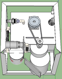
As shown, the offset motor / gear assembly is awkward to mount and will extend beyond the Power Cube frame (one frame member removed for clarity).
I designed a bracket assembly, but have resigned to re-using the bolt holes in the motor's gear assembly for mounting to the plate on top of the power unit:

The bolts must:
* Provide motor support
* Prevent the motor from tilting with increased belt tension / torque
* Allow the motor to slide from side to side to adjust belt tension
October 8, 2017
Preparing for the Solar Power Cube ... Solar Power Cube Working Document
I have to get everything designed in time to order parts for the workshop. The question has now come up for the pulleys and timing belt and how to attach them to the shafts of the motor and pump. The pump side is easy - 1/2" and positioned higher than the motor. Attaching the pulley for the motor is another question, though the motor is somewhat lower than the pump shaft and the motor shaft is threaded on the end.
The initial question is: Do we make the pulley to screw onto the threaded shaft or slide over the lower part of the 20mm shaft (or both)?
The followup question is: Is a lathe (and someone to run it) available in the OSE workshop in good working order for machining and/or threading the pulley to match the shaft?
Also: How do we purchase the pulley material - in discrete pulleys or in "bar" material?
Polytech 5mm Pulleys
Polytech 5mm pitch bar
Note that the motor pulley will have to be longer than the pump pulley for the belt:
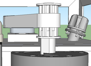
The length of the shaft shown is short and won't extend through the length of the pulley, so we will have to improvise a solution.
The main "gotcha" is that the full specs of the shaft aren't given - like the shaft length and the threads on the end of the shaft.
OK ... I finally found a closeup of the shaft:
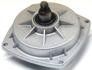
April 22, 2017
Checking out the OSE Wiki pages to see if they are read-write . . .
March 20, 2016
Packing the 3D printer for the return trip. Visit with Alec to see the updates on the Micro House 3 and discuss possibilities for utilizing its solar panels.
March 19, 2016
Workshop began - lots of unloading and preparing supplies for the workshop. Built a printer along with the other participants, but had to leave before testing. One local participant offered the use of a facility nearby, so we packed up and drove there. Successfully tested all printers with only one "smoker", which was repaired for total success. Ended at 12:30 AM and drove back to Factor e Farm.
March 18, 2016
Arrived at OSE, checked out the amazing bok choy growth in the greenhouse and the two new puppies. Helped prepare for the 3D printer workshop. Testing the Porteus software distribution with the 3D printer. Cut aluminum plates for the printers. Packed workshop supplies for the morning trip to the workshop location in Kansas City.
March 14, 2016
OK ... there's been a gap in my log. Concerning the upcoming lab for the 3D printer, the original ISO file for the Linux distro wasn't bootable from a memory stick. The site shows how to convert an ISO file into a "hybrid" file, bootable from optical or memory stick:
Here is the original ISO image that didn't work well for booting from USB sticks:
Here is the image for the 3D printer workshop that has already been converted:
All that needs to be done is do a raw copy of this file to the USB stick using "dd" (Linux), "Disk Utility" (Mac) or some similar disk utility.
Update: The "ddrescue" program is for data recovery and it addresses a different function.
The "dd" command (ie: "Data Dumper") that I mentioned writes data from an input (ie: ISO file) to an output (ie: the USB stick).
First: Identify the device for the USB stick. You can use commands like "lsblk", the "fdisk -l" or the Ubuntu "disks" GUI to find the device. In a single disk system, the "/dev/hda" device is your main hard drive and "/dev/hdb" is often the USB stick. The following writes the ISO to the "sdxx" device:
dd if=Porteus-D3D-Workshop-x86_64-v2.iso of=/dev/sdxx bs=1024b
Please note that the "dd" command performs a raw write and will overwrite the destination device (ie: "of=..."), including all partitioning, formatting, data, etc.
Marcin Notes
sudo apt-get install gddrescue - installs ISO creation program ddrescue
July 26, 2015
Worked on OSE wiki, fixed an issue with the user account approval.
July 25, 2015
I've been working on multiple fixes and updates for the Power Cube design and recently changed it to version 15.7 in the 3D Warehouse. The changes were adjustments from the results of the July Power Cube workshop.
July 15, 2015
Gasifier Workshiop, Day 2 Torched some steel for the gasifier folk. Didn't get much done as there was a personnel issue. Spent time resolving it and documenting jigs. Marcin bought 5 T Shirts and we discussed further sales - I told him that I could ship them individually.
July 15, 2015
MicroTrac Workshiop, Day 1 Focused mostly on finishing the Power Cubes and with the updates to one engine to enable operation with the gasifier.
July 15, 2015
MicroTrac 2.0 Workshiop, Day 3 Worked on Power Cubes and assisted from time to time with the MicroTrac. Welded the plates in the hole punch to prevent drift. The MicroTrac T Shirts arrived - Sold several.
July 14, 2015
MicroTrac 2.0 Workshiop, Day 2 24 links completed! Discussed the idea of a fab shop in a shipping container.
July 13, 2015
MicroTrac 2.0 Workshiop, Day 1: Late start, as Marcin had an eye issue. Worked with Will Turner to make a jig for cutting and punching chain links. Problem with hole punch - dies getting out of alignment. Made first batch of tracks and tested.
July 12, 2015
PC 15.6 Workshop, Day 3: Met with Marcin and Jonathan for planning, then went to the workshop where everyone was gathered and working. Integration day - we found some design issues along the way:
- The 4 x 4 tube at the rear of the engine had to be removed before the engine / muffler could be seated.
- The geometry of the return plumbing could not be used intact and the oil filter had to be unscrewed from the bracket.
- The keyswitch on the old control bracket conflicted with the 4 x 4 tube and had to be rotated 90 degrees.
- The 1 1/2" coupling was made of cast iron and posed a problem for welding the Hydraulic Reservoirs.
- The wiring harness diagram had two wires crossed, which burned out the diodes before the magnetos.
- The bolts securing the bottom of the oil cooler expanded steel to the lower tube could not fit through to the back side of the tube, as the Hydraulic Reservoir was there - so it would have to be secured with short bolts from within the tube (difficult).
These issues were overcome and four of us (Jonathan, Natalia, Will and I) worked on one Power Cube and finally got it going.
July 11, 2015
PC 15.6 Workshop, Day 2: Met with Marcin and Jonathan for planning, then went to the HabLab for discussion before continuing. Continued welding tanks and started on assembling the modules - oil cooler, return plumbing, pressure plumbing, After burning out the diodes, found some replacements in the HabLab, replaced them and got the Power Cube working around midnight.
July 10, 2013
PC 15.6 Workshop, Day 1: Met with Marcin and Jonathan for planning, then went to the HabLab for introductions and lecture. Spent the time cleaning up the shop in preparation for the workshop. Proceeded afterward to the workshop, held the safety briefing and started the build. We planned to do the "dirty stuff" today, cutting steel & welding. The tanks took the full 3 days to complete. Moved the LifeTrac near the door, ran the hoses between it and the iron worker and cut steel for the tank end plates. Only one MIG welder worked initially. Marcin told me what had to be done and I disassembled, replaced liner and wire on two other welders to get them working.
July 9, 2013
Continued cleaning the shop and organizing for the workshop.
July 8, 2013
Arrived at KCI. Marcin arrived in the truck and we drove to MoKan Fasterners for bolts, Harbor Freight for tools and then for Factor E Farm. Spent several hours resolving automotive issues. Spent time organizing the shop and layout out supplies.
June 19, 2015
Updated MediaWiki with extension to require admin approval for new accounts. The other means of blocking spambots just wasn't working. Uploaded newest Power Cube 15.6 BOM.
June 1, 2015
Updated MediaWiki to enable ReCaptcha. Still having some issues with bogus user registration.
January 17, 2015
Power cube arrived this week (Yahoo!). After the shipment, the shipping company charged me an additional $84.60 for a "limited access fee". They claimed the fee is standard across the shipping industry when delivering to schools/universities.
January 13, 2015
Power cube shipment delayed to avoid holiday shipping maddness. Shipped Power Cube kit (ie: Power Cube, less engine & battery).
October 26, 2014
Received an order for a Power Cube, Version 7, less the engine. I've been updating the Sketchup model to include the pressure relief valve and the updated BOM for current pricing. Now to complete the model & BOM and start ordering parts tomorrow. I've also begun inquiries about information about sensors for the hydraulic flow, pressure and temperature - to accommodate new power cube certification requirements.
MicroHouse 4 Workshop
Attended this workshop to get better acquainted with MicroHouse design and CEB construction techniques.
Tue Sep 30, 2014
Back to Dallas.
Mon Sep 29, 2014
Met the electrician from the power company with connectors and tools. Replaced connectors and added MicroHouse wiring. Installed electrical conduit, elbows and ran wiring from the electric panel to the MicroHouse for all lights, sockets, stove and dryer. Other crews completed the roof and began installing windows.
Sun Sep 28, 2014
Painted initial coat on the plywood side of lower roof modules to save time later. Upper roof module construction using screws, 2" x 6" x 16' boards and struts. Other crews installed the roof modules. Dug trench and set conduit into ground for incoming and outgoing cables. Connected the incoming cables to the box main power and prepared connections for the cables to the MicroHouse 3. Secured the electrical connections on the MicroHouse, as it is to "go live" in the morning.
Sat Sep 27, 2014
Lower roof module construction using screws, 3/8" plywood, 2" x 6" x 16' boards and struts.
Fri Sep 26, 2014
Completed digging the trench for the electric cable. Met the electrician from the power company, who opened up the panel only to find that we would need replacement connectors to continue. Closed the panel and informed Marcin of the situation. Worked with several teams to set the CEB blocks for the walls and to make additional blocks from soil and lime. Walls mostly completed today.
Thu Sep 25, 2014
Worked on Micro House misc tasks - including preparing landings and placing the hydronic stove. Checked out the electric panel at the MicroHouse and prepared it to "go live". Drove to Menard's to get supplies for wiring the electric cables from the Micro House to the panel on the workshop.
Wed Sep 24, 2014
Caught a ride to OSE, Missouri with Marshall (from Austin). Checked out the progress made on the Structural Frame Power Cubes and gave a few suggestions for completing one kit.
Sat Sep 14, 2013: 50 HP Power Cube Design
We've had a lot of discussion about the new PowerCube and the new LifeTrac designs and I think I have wrapped my mind around the new frame design. Here is a screenshot:

Latest 50 hp Power Cube Suggestion: File:PowerCube 35 Tom.zip
Thursday, July 8, 2013
Drove up to Missouri and to Factor E Farm for the Power Cube / LifeTrac build for Blair Grocery in New Orleans. Spent time designing the new Power Cube with the Kubota diesel engine. Drove to secure the engine, radiator and other parts necessary for the build. Used Sketchup to update the design according to the newly secured Kubota engine. Cut steel for the new 36" frame and began gathering other necessary parts - such as the fan and oil cooler.
James Slade arrived and received instructions to assist with Power Cube development. The crew from Blair Grocery arrived and were oriented for assisting in the build of the LifeTrac. The LifeTrac and Power Cube development proceeded at the same time.
I headed back to Dallas and a few days later, the LifeTrac was functioning and was loaded onto the trailer for transport to New Orleans with the 27 hp Power Cube and the unfinished Kubota Power Cube. The transport stopped at my farm in East Texas, where the Kubota Power Cube was completed, loaded in the LifeTrac, tested and then loaded for shipping to New Orleans - where it was tested successfully.

Latest Kubota Power Cube Design: File:PowerCube Kubota.zip
Thursday, May 25 2013 (Date needs verification)
It's been some time since my last update. The latest activity concerns the new Power Cube design - using a Volkswagen engine. I expect to meet with Jay early this next week to complete the rebuild of the engine and secure the engine. I still have a few more parts to get - especially for mounting the shaft coupling and engine mounts. I have been working on the component layout for the new Power Cube - it will be quite different from before, as the engine/pump mounting is horizontal rather than vertical. Also, the plumbing and engine are larger and heavier and I will be adding a pressure relief valve. The sizing of the hydraulic pump has been a big issue and is documented here:
http://opensourceecology.org/wiki/Hydraulic_Hose_Sizing