User:Dorkmo/Builds/SteamEngine
steam engine
building based on this sketchup model [1]
feel free to make comments in the discussion tab.
to do
calculate desired steam flow through valves http://en.wikipedia.org/wiki/Flow_coefficient
- through crank shaft oil line from split pillow block to arm split bearing
- printable shaft hole alignment jig for 1" holes
- 2 position solenoid valve
hardware
- ace hardware
- nylon parts for copper spool
- all thread rod
- grainger
- aluminum tube spacer
- made in usa pipe fittings
Engine Management System
design work
oil
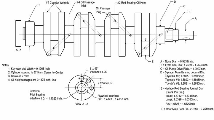
crank weight
need to boil this down to some sort of math formula:
http://groups.google.com/group/open-source-steam/browse_thread/thread/b2b048910b53bf17
- Wow,
Actually, that's my primary job at GM, balancing crankshafts, flywheels, dyno components and so on for all the stuff that moves through Engineering World Headquarters. You could write a book on this subject, people have, actually....I've written a few really long articles. You can find one of them at: http://steamautomobile.com/phorum5214/read.php?1,18749 and scroll to the bottom of the page and download the file Engine_Balance_2003.pdf. The general rule of thumb, if balance shafts are not involved, is that you need to attach a weight to each crankpin equal to the rotating masses attached to that pin, plus half the reciprocating masses. NOTE: You can NOT dynamically balance a crankshaft without specialized equipment, dynamic balance being a property of objects that are long enough in relation to their diameter to possess significant rocking couples. You can balance a single cylinder crank acceptably enough, if you are careful and the crank is carefully built and symmetrical to begin with. If you plan on rebalancing the LS-9 in your ZR-1 Corvette, please put my name down as beneficiary. Anyhoo....the reciprocating masses would be the pistons, rings, wrist pin, wrist pin bushing and so on. The rotating mass would be the crankpin bearing or bushing. The connecting rod is where things get hinky, the big end makes a circle because it is on the crank and the small end goes uppy-downy in the cylinder bore. It's one of those situations where the answer is "YES" if asked whether the rod is reciprocating or rotating mass. What we end up doing is weighing each end of the crank to properly allocate rotating and reciprocating masses. Of course, being in the business and all that we have a sooper dooper special custom built scale that does the job instantly. That's nice but not necessary, just cuts down on wasted time. What you do is get an electronic scale and put a couple of spacers on top along with a steel pin, and then zero out the scale. You set up another pair of spacers next to the scale, and also have a steel pin ready. The rod is then suspended from the spacers, through the big and little ends of the rod, by the pins. The spacers should be such that the rod is parallel to the ground. If the big end is on the scale the weight on the readout is equal to the rotating portion of the rods mass, if the little end is on the scale, it is reading the reciprocating portion. Now flip the rod end for end and repeat. Now, as a double check, weigh the rod and see if the total weight equals the reciprocating and rotating weights. Repeat as necessary until you get a solution that jives. Now that you have the reciprocating and rotating masses summed up, you need to make some sort of weight to put on the crank pin. This weight will be equal to 1/2 the recipocating mass plus the rotating mass. There is a logical explanation for that and you can find it in the pdf file mentioned above. We refer to this as a 'bob weight' or a 'ring weight'. Most speed shops use universal weights to which they can add extra mass equally to each side until getting the right weight. I make them on a lathe to fit the crankpin diameter, and also to have no more than .001 inch side play so the weight can not move fore and aft to change the load distribution AND I also statically balance the weight on a flywheel balancer when I am adjusting the weight to the desired value so as to guarantee that the center of gravity is dead in the middle of the weight. For all practical purposes the crank sees the weight as a point source located at the CG, if the CG is not coaxial to the crank pin then the position of the weight (and the mechanical advantage) shifts depending on what angle the weight is bolted onto the crank. Now, the old timers building small steam engines calculated the weights and measured out a long hank of plumbers lead until they got a piece that was the correct weight. Then they would slowly and meticulously wrap it on the crank pin taking painstaking care to lay the winds on tightly and evenly so as to achieve the most equal distribution around the pin as possible. This is hardly up to racing or factory specs, but I have done that for a few single cylinder test engines when time didn't permit constructing a special weight and the universal weight set I keep for emergencies didn't go small enough. Since they weren't pushing the test mills to 8,000 rpm, no one saw any problems with the balance. Have I scared you off yet?
- -D
Ken
I look forward to seeing what you come up with, I'd never laugh at someone who is taking the effort to research the topic and taking pains to develop a rational plan of action based on that research. When someone does little research, assumes almost instant command of the topic and then proceeds to repeat the classic errors that have been debunked for generations....then I tend to laugh.
Your spreadsheet looks about right. When calculating the masses to design the crank and counterweight, it is vital to know the location of the centers of gravity. Two equally heavy counterweights respond very differently depending on how far the center of gravity is from the axis of rotation.
Counterweights are often strangely shaped, and it's a bit difficult to determine what their weight and CG will be beforehand. If you have access to better CAD programs, this information is at your fingertips. The old timers sometimes got very close with drafting tools, a knife, scale and construction paper. They would draw out the counterweight on a piece of construction paper and cut it out very carefully, then weigh the paper on a precision scale. Then they would cut out a square from the same material and weigh it. If the paper square was 5 inches on a side, the area was 25 square inches. If the weight was 2.5 ounces, then the weight was 0.10 ounces per square inch. From this point it was easy to determine the area of the counterweight and by multiplying by thickness obtain volume. The same heavy paper model was good for finding center of gravity. You would block a metal rule edge up on the table, lay the paper cutout on it and move it back and forth til you got it to balance. If the part was symmetrical, by carefully marking the line described by the rule, you could find the CG. If not too symmetrical, you would rotate the part 90 degrees on the rule and balance again, the intersection being the CG. To determine the unbalance force, you then merely had to measure the distance between the CG and the center of rotation and multiply by the part weight.
OK, I admit these are kind of crude methods in the computer age, but perfectly suited for a hacksaw and welder.
Regards,
Ken
http://en.wikipedia.org/wiki/Centroid
http://www.grc.nasa.gov/WWW/k-12/airplane/cg.html
http://www.alexschreyer.net/projects/centroid-and-area-properties-plugin-for-sketchup/
https://docs.google.com/spreadsheet/ccc?key=0AgxMMqGvwTM-dEswZUZ6d1hRNWpOeWlhMGlZRkdsdWc
solenoid
ive been thinking it might be best to use a non magnetic metal at the top and bottom of the solenoid
maybe a stainless steel or perhaps aluminum
http://www.azom.com/article.aspx?ArticleID=1140
thinking of using a two small 2 position solenoid valves for the in out. mounted with four holes.
http://www.ascovalve.com/Applications/Products/Solenoid2WayData.aspx#HotWater
http://en.wikipedia.org/wiki/Flow_coefficient
progress
so far ive built a solenoid valve but i still need to test it. im slacking on that, theres a big air compressor i can use but its out in the country.
trying to figure out the final parts for piston and sleeve
- have to match up all the diameters of everything
90% i like these parts:
outer sleeve: 4-1/2" 12 gauge tube
brass sleeve: 104mm ID
piston ring: 241 teflon o-ring 1/8" thick
outer piston: 4" 12 gauge tube w/ .078" cut for ring to sit in
top of piston: steel plate, not sure yet
11/31/11
made a pattern to tranfer punch where holes are to be drilled
[[2]]
there should end up being seven different sets. not sure if pages will be reusable after punching through?
need to put a ruler on the printouts so peeps can verify they printed to the right size.
12/1/11
spooled two more solenoids. need to get more nylon washers for #4.
need to find online retailer for nylon stuff
12/8/11
received most of the materials for the build.
going to do some preliminary stuff and then get ready to go to austin to meet up with thad.
drilled some holes. need to get a 5/8" and 4-1/2" drill bit.
might change the design to 3/4" rod instead of 5/8". was hard to find a bit. drill bit sets go up to 1/2" and hole drilling bits start at 3/4". but not sure if they could cut through 1-1/2" square tube, will look into.
1/27/12
got all the holes cut in the frame pieces.
brass sleeve is a little too big on o.d. might order smaller gauge steel pipe.
matching up holes. making bigger where needed.
need to make pipe tee support holes a little bigger.
2/6/12
had a thought to move the spring around so the seal was on the top of the plate to save room in the cylinder.
will still have the height of a 1/4" nut + a little extra threaded rod occupying room in the cylinder.
i updated the diagram here User:Dorkmo/Ideas/Steamvalves
going to shop and see if i can find an appropriate spring.
2/7/12
i ordered a couple different 2" long compression springs from grainger, not sure how stiff it needs to be.
- i dont know much about springs, seemed okay to sped a few bucks to try some different stuff
- probly going to need to edit spacer length to move magnet closer to clynder to get the 2" spring to be compressed a little.
also ordered some 4-1/2" 16 gauge pipe for the cylinders. i think i might have recieved 11 gauge instead of 12 gauge so thats why it was too thick. 16 might be small, not sure if itll be a problem.
need to coil another magnet bc i guess i lost one
still need to decide how to get solenoid wires through the plate steel
- heat shrink + silicone?
once i file all the holes so the bolts all go in im going to apply some wood hardener to some of the stuff. not sure what effect its going to have but hope it wont be bad.
2/8/12
only had time to drill one 5/8" hole today in the pillow block mounts. three more to go, hope fully tomrrow. then the holes for block bolts them selves.
my mum took me to the movies. nice little film about urban life. nice overview, didnt get super in depth. would be good required watching for any town mayor. http://urbanizedfilm.com/
think i might ask for some math help on the forum tomorrow about weighting the crank shaft and the size of the holes for the valves. i keep putting that work off :/
2/12/12
cut a couple threaded rods to finish top side
installed pillow blocks and mounts
got 95% of structral stuff done. just not the side walls. going to tear down later to paint and seal.
will work on pistons next then crank arms then shaft then solenoids then oil pump system yadda yadda
2/14/12
set up a jig using the sheet steel and four hack saw blades to try cutting grooves for piston rings. seems to cut accurately but takes a long time. worried i might be going to deep. but not much play between sleeve and piston.
tried welding for the first time on attaching piston wall (4" pipe) to top of the piston (skinny cut of round bar). went okay. might jb weld gaps.
going to continue with grooves. then mess with attachment to crank arm.
4/19/12
might order some 227 orings to seal around valves
4/27/12
227 were too thick
also ordered eight 045 for the piston rings so wouldnt have to cut away as much material
crank is welded but need to straighten out a little somehow
need to weld on weights still
working on crank arms
4/28/12
might need to go with 10 gauge 1-1/2" pipe for crank instad of 11gauge. a bit of a gap.
www.discountsteel.com/items/Electric_Welded_ERW_Round_Steel_Tube.cfm?item_id=201&size_no=81
need to find out if brass sleeve will go into hot 4-1/2 metal
thinking about oil pump options. belt driven or electric motor? gear pump or centrifugal? what would have the best chance of being 3d printed in the future? will lag of gear driven put too much wear on?
4/29/12
ordered a foot more of 2 x 3/8 steel for crank weights. total need is a little less than 4 feet.
www.grainger.com/Grainger/Rectangular-Bar-2HHD2
going to cut 3/4 holes for valves in plate
a little less the 1/2 a square inch area.
had some drill problems with 1-1/2 holes for crank arms.
4/30/12 need two washers in valve so spring distance be adjusted
should be able to have solenoids hooked to electronics tomorrow
5/20/12
think it might be better to put angle alluminum for the crank arm mount on the piston
5/22/12
i finished two crank arms. im pretty happy with one but the other the 1 inch side isnt perfectly perpendicular so the other side is off by about half an inch. the piece i used wasnt cut very straight so when i welded it was off. i layed it all out sideways flat and lifted the sheet to the halfway point.
need to insure proper cut or use different method when welding.
had to cut into sheet a little to accomidate bolt. need to update sketchup.


