A-Z Instructionals: Difference between revisions
| (4 intermediate revisions by the same user not shown) | |||
| Line 1: | Line 1: | ||
'''THIS PAGE IS FOR THE CEB PRESS''' | '''THIS PAGE IS FOR THE CEB PRESS''' | ||
This page gives you all the information you need to make your CEB Press from stock steel and parts. The steps in '''Mechanical Fabrication''' and '''Electronic Components''' are independent of each other, but within each category, the suggested order should be followed. Once you finish both, you can continue on to '''Final Machine Integration'''. At that point, your machine can be used. | This page gives you all the information you need to make your CEB Press from stock steel and parts. The steps in '''Mechanical Fabrication''' and '''Electronic Components''' are independent of each other, but within each category, the suggested order should be followed. Once you finish both, you can continue on to '''Final Machine Integration'''. At that point, your machine can be used. | ||
=[[CEB/ | |||
Also available is a PDF of the instructions listed here: | |||
[[Media:CEB_a-z_Build_1.0.pdf|CEB A-Z Fabrication Instructions 2011]] | |||
=[[CEB Press/Bill of Materials|Bill of Materials]]= | |||
=Mechanical Fabrication= | =Mechanical Fabrication= | ||
| Line 33: | Line 40: | ||
<li>[http://makeprojects.com/Project/Prepare-the-Hopper-Sheet-Metal/1723/1 Hopper Sheet Metal] | <li>[http://makeprojects.com/Project/Prepare-the-Hopper-Sheet-Metal/1723/1 Hopper Sheet Metal] | ||
<li>[http://makeprojects.com/Project/Hopper-Mounting-Plate/1732/1 Hopper Mounting plate] | <li>[http://makeprojects.com/Project/Hopper-Mounting-Plate/1732/1 Hopper Mounting plate] | ||
<li>[http://makeprojects.com/Project/CEB-Soil-Grate/1731/1 Grate] | <li>[http://makeprojects.com/Project/CEB-Soil-Grate/1731/1 Grate]</ol> | ||
===Machine Core=== | ===Machine Core=== | ||
| Line 81: | Line 88: | ||
=Final Machine Integration= | =Final Machine Integration= | ||
#[[CEB Press/Manufacturing Instructions/Mount Solenoid Valve Set And Controller Box|Mount Solenoid Valve Set And Controller Box ]] | #[[CEB Press/Manufacturing Instructions/Mount Solenoid Valve Set And Controller Box|Mount Solenoid Valve Set And Controller Box ]] | ||
#[[CEB Press/Manufacturing Instructions/ElectrohydraulicIntegration|Electrohydraulic Integration]] | #[[CEB Press/Manufacturing Instructions/ElectrohydraulicIntegration|Electrohydraulic Integration]] | ||
#[[CEB Press/Manufacturing Instructions/Code Upload|Code Upload]] | #[[CEB Press/Manufacturing Instructions/Code Upload|Code Upload]] | ||
Latest revision as of 01:36, 27 December 2011
THIS PAGE IS FOR THE CEB PRESS
This page gives you all the information you need to make your CEB Press from stock steel and parts. The steps in Mechanical Fabrication and Electronic Components are independent of each other, but within each category, the suggested order should be followed. Once you finish both, you can continue on to Final Machine Integration. At that point, your machine can be used.
Also available is a PDF of the instructions listed here: CEB A-Z Fabrication Instructions 2011
Bill of Materials
Mechanical Fabrication
The purpose of this section is to build and assemble all mechanical components of the CEB. You must first cut the steel, then fabricate individual parts, then assemble them, and then paint the machine.
Steel Cut List
- Cut the steel into the following lengths.
- Label and separate cuts by "Step" number so you can easily find cuts for each step during the fabrication stage.
- Note: Item Number and part number refer to CAD information. This is un-necessary if you are following the fabrication steps listed.
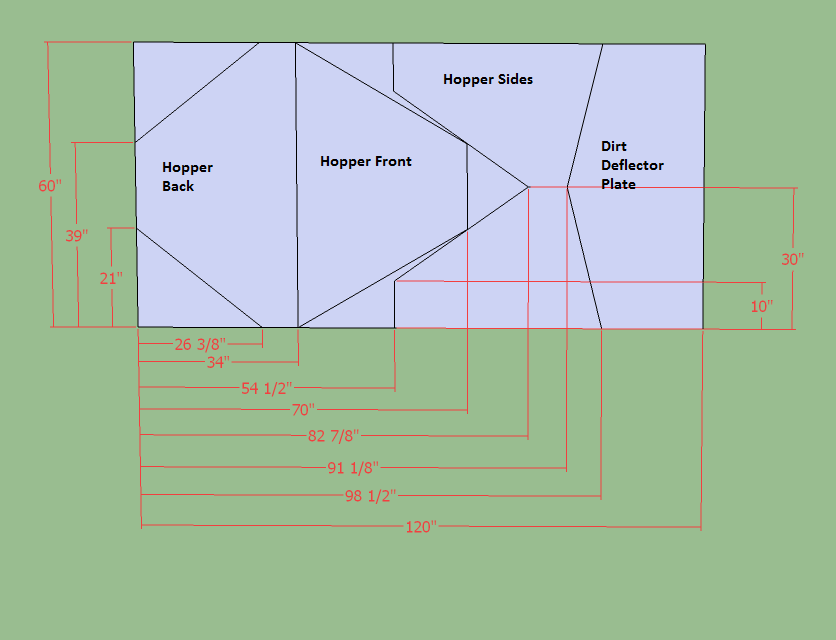
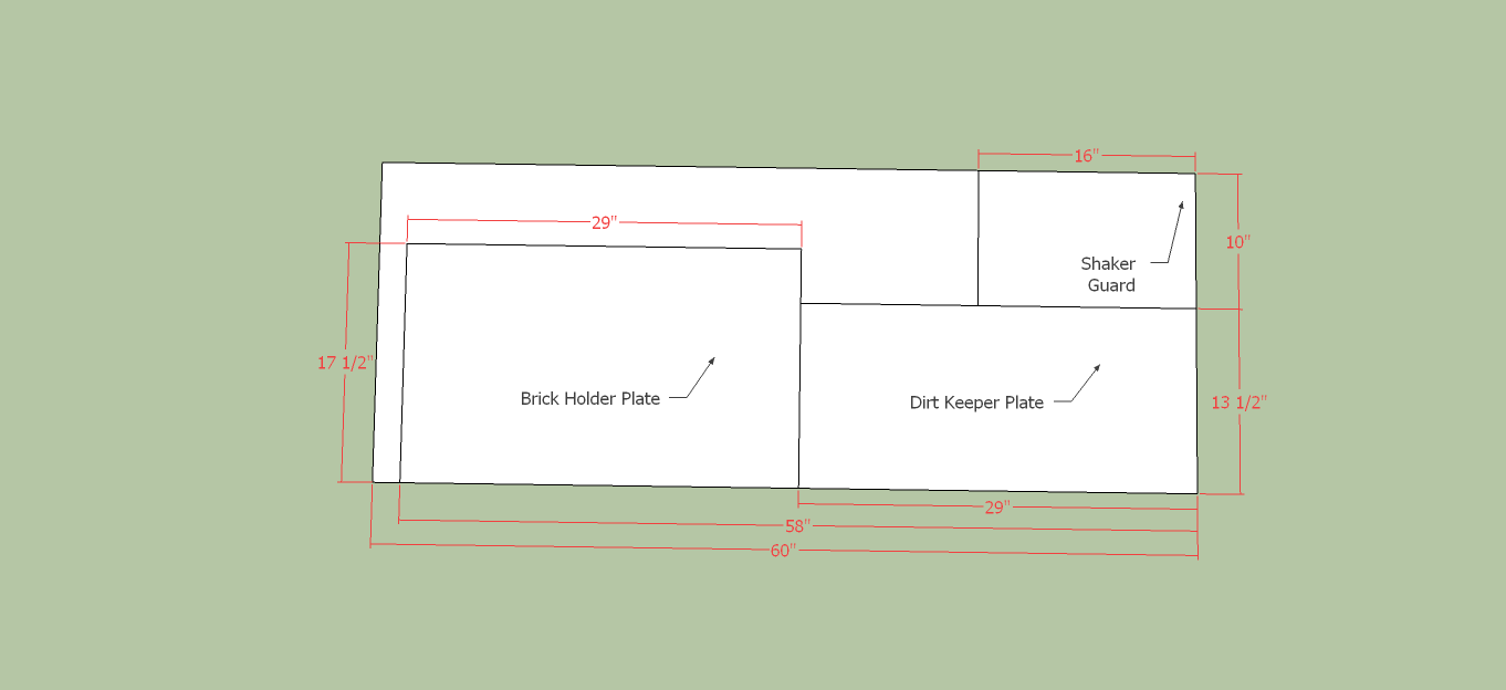
- Also, from the sheet, torch the Hopper Sheet Metal and the simple plates.
Link to printable page.
Parts Fabrication
The purpose of this section is to assemble the cut steel into individual parts and assemblies.
- Please see this spreadsheet for what steel each step requires.
Structural Components
Shaker
Hopper and Grate
Machine Core
Main Frame Preparation
- Wide Cylinder Supports
- Main Frame Small Components
- Main Frame U-Channel Prep-Still needs fab drawings
Main Frame Assembly
- Assemble U Channel
- Fit the Main Cylinder
- Stretch the frame
- Weld the spacers
- Install Small Components
- Fit the Drawer Members
Hydraulics
Parts Assembly
The purpose of this section is to assemble all of the parts you made in the parts fabrication section.
- Assemble the structural components
- Assemble the Soil Loading System
- Shaker Assembly
- Adjust the Drawer
- Install the secondary cylinder
- Hard-line the main cylinder
Paint
- Cover the hydraulics and any other place that should not be painted.
- Check all external surfaces for sharp edges and smooth with angle grinder.
- Remove any surface rust with wire brush and / or sandpaper.
- Apply a thorough coating of paint to all steel surfaces.
- Allow 24 hours to dry before handling.