D3D CNC Circuit Mill: Difference between revisions
S Oberloier (talk | contribs) |
(→Basics) |
||
| (122 intermediate revisions by 8 users not shown) | |||
| Line 1: | Line 1: | ||
=Basics= | |||
*A CNC mill used for PCB Milling | |||
*Can't make as small of traces as a lithography+ethcing system, BUT it is far cheaper and easier to use (ie no chemical etchants or photoresists needed) | |||
*Uses the [[D3D Univeral Axis]] | |||
*D3D circuit mill - https://mi_shell.gitlab.io/models_online/ose_webgl/d3d_circuit_mill.html | |||
=Genealogy= | |||
*The CNC circuit mill took another turn in 2019 with the [[Open Source Microfactory STEAM Camp]], where we built the D3D Universal 3D printer with a hole-drilling capacity for circuit boards. | |||
*[[D3D CNC Circuit Mill]] - built in 2018 with the Universal Axis. | |||
*We also built [[HydraFabber]] in 2014 - which used a low cost spindle. See [[John Log]] for pictures of the mill. This is prior to the [[Universal Axis]], which was introduced in 2016. The spindle was built and run, but we did not mill any boards. | |||
*Yoonseo Kang built a circuit mill while at OSE in 2012. See [[Yoonseo Log]] - as a power user, Yoonseo developed a lot of useful proofs of concept, such as the [[Cold Saw]] and [[Tooling Plate]], among others. Specifically - v1 was built, and v2 was not. These were pre-Universal Axis. | |||
**[[CNCCM]] | |||
**[[CNCCMV2]] | |||
=3D Model= | |||
*You can rotate, zoom, and explode: | |||
<html><iframe src="https://mi_shell.gitlab.io/models_online/ose_webgl/d3d_circuit_mill.html" width="960" height="540"></iframe></html> | |||
{{Hint|July 2018 - OSE Germany is working on a version of their MPPT Solar Charge Controller which can be milled with the OSE D3D CNC Circuit Mill - https://github.com/LibreSolar/MPPT-Charger_20A/issues/28 }} | |||
<html><iframe src="https://www.facebook.com/plugins/post.php?href=https%3A%2F%2Fwww.facebook.com%2Fmarcin.jakubowski.378%2Fposts%2F10214031283793314&width=500" width="500" height="752" style="border:none;overflow:hidden" scrolling="no" frameborder="0" allowTransparency="true" allow="encrypted-media"></iframe></html> | |||
=Publication= | |||
Published in ''Inventions'', http://mdpi.com/2411-5134/3/3/64 | |||
Preprint - https://www.preprints.org/manuscript/201808.0233/v1 | |||
=Build Instructions= | |||
*Drill frame | |||
*Do Cut List below - rods, belt | |||
*Cut bed plate | |||
*Assemble electronics mounting plate | |||
*Assemble spindle in holder | |||
*Test electronics - motion | |||
*Test calibration code | |||
*Run a milling job | |||
=Cut List= | |||
(400, 350, and 300 lengths would work) | |||
*Belt - x - [2] 29" | |||
*Belt - y - [2] 33" | |||
*Belt - z - [2] 23" | |||
*Rods - x - [4] 14"- = 56" | |||
*Rods - y - [4] 16"- = 64" | |||
*Rods - z - [4] 11" = 44" | |||
*Frame if welded from flats - [24] 1/8"x1"x15" flats - | |||
*Electronics mounting panel - 1/10" plexiglass - 8"x16" | |||
==Rods if Using 6' Stock== | |||
===Try 1=== | |||
*If use 6 foot stock- 72" - 4x11=44 + 28 = 72. | |||
*4x16 = 64 (8 left over). It's useful to rework design to allow for 8" rod on Z | |||
*2x14 = 28 (44 left over) | |||
*3 rods needed for 162" = 13.5' | |||
===Try 2=== | |||
*4x14 + 16 => perfect. | |||
*3x16 + 2x11 = 70 for 2" left over- great. | |||
*2x11 = 22 with 50 left over. Nice. | |||
Continuing: | |||
*3x16= 2" left over from last one. | |||
*4x14 + 16 => perfect | |||
*1x16+4x11 = 60 - 12 left over. | |||
''Italic text'' | |||
=July 2017= | |||
[[File:d3dmill.jpg|500px]][[File:d3dmill2.jpg|500px]] | |||
<html><iframe width="560" height="315" src="https://www.youtube.com/embed/Epit8c9zp8Q" frameborder="0" allowfullscreen></iframe></html> | <html><iframe width="560" height="315" src="https://www.youtube.com/embed/Epit8c9zp8Q" frameborder="0" allowfullscreen></iframe></html> | ||
<html><iframe width="400" height="240" src="https://www.youtube.com/embed/OkZ0ynYMTWM" frameborder="0" allowfullscreen></iframe></html> | |||
<html> | |||
<iframe src="https://www.facebook.com/plugins/post.php?href=https%3A%2F%2Fwww.facebook.com%2Fmarcin.jakubowski.378%2Fposts%2F10211234901725510&width=500" width="500" height="666" style="border:none;overflow:hidden" scrolling="no" frameborder="0" allowTransparency="true"></iframe> | |||
<iframe src="https://www.facebook.com/plugins/post.php?href=https%3A%2F%2Fwww.facebook.com%2Fmarcin.jakubowski.378%2Fposts%2F10211234878364926&width=500" width="500" height="503" style="border:none;overflow:hidden" scrolling="no" frameborder="0" allowTransparency="true"></iframe> | |||
</html> | |||
=Comparison to Industry Standards= | |||
[[File:cnccmcomparison.png]] | |||
Notes: precision is not defined here. If it is positioning accuracy, Othermill appears to be 0.003 (see [[D3D_CNC_Circuit_Mill#Industry Standards]]. | |||
=BOM= | |||
<html><iframe src="https://docs.google.com/spreadsheets/d/e/2PACX-1vRbKqzzLcyhpribpx8T8_MTGTbTJfJ9TeVOnC2x3rxSSNWICQR5ak-GmamhFq6s1HI3ZzImYb--1goN/pubhtml?widget=true&headers=false" height=500 width=900></iframe></html> | |||
[https://docs.google.com/spreadsheets/d/1IizDF9765JaS_Z6JcFpuqDRS9ar34UeEUUDC40bA9NM/edit#gid=0 edit] | |||
==Other Supplies== | |||
Single Sided Copper Clad Laminate PCB Circuit Board 4X3 (50pcs) | |||
Paramount CCL | |||
Link: http://a.co/3YcKSBe | |||
Xuchuan 10Pcs PCB Print Circuit Board Carbide Micro Drill Bits 0.3-1.2mm | |||
Xuchuan | |||
Link: http://a.co/0KviIvf | |||
JIUWU 1.0mm Tungsten Steel Carbide PCB CNC End Mill Engraving Bits Milling Machine Pack of 10 | |||
by JIUWU | |||
Link: http://a.co/1CL0H32 | |||
You can try these tools out - they are inexpensive and may yield good results for milling traces. But if you run into issues, the tools are likely chipping | |||
Autek 10x Titanium Coated Carbide PCB Engraving CNC Bit Router Tool 30 Degree 0.1mm Tip(J3.3001Tix10) | |||
by Autek | |||
Link: http://a.co/6UR8F9T | |||
Instead it may be good to opt for higher quality milling tools. They should last a good long while: | |||
Universal Milling Tools | |||
100% Carbide universal milling tool for milling printed circuit board isolation tracks. V-shaped profile for variable milling width. 1.42" (36 mm) overall length. | |||
https://www.lpkfusa.com/Store/pages/ProductDetail.aspx?cat=11%2f42&cid=42&pid=30 | |||
All Industrial Tool Supply TR72020 Dial Indicator (Magnetic Base and Point Precision Inspection Set), 1 Pack | |||
by All Industrial Tool Supply | |||
Link: http://a.co/5EgkHa0 | |||
Software: | |||
See this link - it has all of the software we used and then some: http://opencircuitinstitute.org/content/software | |||
Additionally here is my web-based leveling utility: http://voltfolio.com/utilities/levelgcode.html | |||
https://www.lpkfusa.com/Store/pages/ProductDetail.aspx?cat=11%2f38&cid=38&pid=76 | |||
Sorry I must make one amendment - I linked the incorrect milling tools from LPKF. Here are the correct ones: | |||
https://www.lpkfusa.com/Store/pages/ProductDetail.aspx?cat=11%2f38&cid=38&pid=76 | |||
=vBOM= | |||
Visual BOM: | |||
<html><iframe src="https://docs.google.com/presentation/d/e/2PACX-1vTkcBnXyrpmStHdqDtioOe9lb5GUGlJxf2HVlxEbGGo8fFi-8Y4rtbhJVoy3lxwCkOZSMGbibmMNCHa/embed?start=false&loop=false&delayms=3000" frameborder="0" width="960" height="569" allowfullscreen="true" mozallowfullscreen="true" webkitallowfullscreen="true"></iframe></html> | |||
[https://docs.google.com/presentation/d/1LP9yQnlysYbAlETJ4mF5AaY-uncKPj45ZGzdgVycWyg/edit#slide=id.g1861bf60d5_0_6 edit] | |||
=Calculations= | |||
<html><iframe src="https://docs.google.com/presentation/d/e/2PACX-1vRQ62eUra6T3xcmDnQENOw9guBCj4GbT6dI1xdEtXsgrXBt6fnm6RPtAv72GhSBpnf147bNjT4b2CGY/embed?start=false&loop=false&delayms=3000" frameborder="0" width="480" height="299" allowfullscreen="true" mozallowfullscreen="true" webkitallowfullscreen="true"></iframe></html> | |||
[https://docs.google.com/presentation/d/1qtsefqGm-iR2exSDenuGyYgVrFATqNqr0IAUAY3NnZQ/edit#slide=id.g3d3474830c_0_20 edit] | |||
==Sources== | |||
*[[File:backlash_Pattern.odg]] - editable drawing of backlash pattern. | |||
=Electronics= | |||
<html><iframe src="https://docs.google.com/presentation/d/e/2PACX-1vQQ0ILuYF1F25cOFhsVyRZnGZ6BGaSNwz6q9EP-8G0CnQ9ugILrRVKSrfrnGkdSBczDMsqXxKhLQtuJ/embed?start=false&loop=false&delayms=3000" frameborder="0" width="480" height="299" allowfullscreen="true" mozallowfullscreen="true" webkitallowfullscreen="true"></iframe></html> | |||
[https://docs.google.com/presentation/d/1hcExFY5c_PzEYEX7zXtdbi6mP2TudXlQHtWcIKBMmmE/edit#slide=id.g3d3474830c_0_0 edit] | |||
==Source== | |||
*Diagram in Libre Office - [[File:D3D_Circuit_Diagram.odg]] | |||
=Photo Album= | |||
*On google photos - [https://photos.google.com/u/1/share/AF1QipPfvIn6M9N21e7d9s1KYNsGj_OBJlwJ2ZUXo23-XJBkBjDgwfOmzoeXMzDBMCQQpA?key=ZVh5YzRVeFNwcUNqbUtqUUVSSEJhLWVFcW9tdTRn] | |||
=Videos= | |||
*Mill Experiment - Backlash Compensation Stress Test - [https://www.youtube.com/watch?v=ZeWZ5j9NPi0] | |||
*Leveled circuit - '''holder slides at the end''' - [https://www.youtube.com/watch?v=UkRM9UQ5hi4] | |||
*Mill Experiment - Large Leveled Circuit Take 2 - [https://www.youtube.com/watch?v=Fi_GUrzeWkQ] | |||
*Auto Probing Experiment - [https://www.youtube.com/watch?v=htEpllowrB8] | |||
*Stepper driver breakout board - [https://www.youtube.com/watch?v=reH9pmfDJGQ] | |||
=Workshop Preparation= | |||
<html><iframe src="https://docs.google.com/presentation/d/e/2PACX-1vT1kFTkaYeiD0Mv8J-NwLEwdT32JWCdcmWpF6gz_kTHqw4y9ohNb3Rqyv7KjBxJLkMFrO836gYPxrgY/embed?start=false&loop=false&delayms=3000" frameborder="0" width="480" height="299" allowfullscreen="true" mozallowfullscreen="true" webkitallowfullscreen="true"></iframe></html> | |||
[https://docs.google.com/presentation/d/1hAPgRZMJV3NI8xI2DTi2mJAdR4a_690SPCm0Rgdhbtw/edit#slide=id.g39a872edb1_0_32 edit] | |||
=Development Template= | |||
<html><iframe src="https://docs.google.com/spreadsheets/d/e/2PACX-1vSU_mLm_aYw0UeBEJc-oU-YeFc1-b5RktKyDstz2XDdWEZBKtUIgHBQlXybfASNt_jdYVPOsnYx-M1Q/pubhtml?widget=true&headers=false" height=500 width=500></iframe></html> | |||
[https://docs.google.com/spreadsheets/d/1f4ooVmRzw47MWcpTiTW165Ua9ypRRZ4yj-DObs-Lnyk/edit#gid=1 edit] | |||
=Burndown= | |||
<html><iframe frameBorder=0 scrolling="no" src="https://osedev.org/graph/weekly/burndown/D3D%20CNC%20Circuit%20Mill?start=5/22/2018" height=300 width=600></iframe></html> | |||
=Feb 2018 Update= | |||
<html><iframe src="https://www.facebook.com/plugins/post.php?href=https%3A%2F%2Fwww.facebook.com%2Fmarcin.jakubowski.378%2Fposts%2F10212948838292853&width=500" width="500" height="613" style="border:none;overflow:hidden" scrolling="no" frameborder="0" allowTransparency="true"></iframe></html> | |||
=September 2017 Update= | |||
<html><iframe src="https://www.facebook.com/plugins/post.php?href=https%3A%2F%2Fwww.facebook.com%2Fmarcin.jakubowski.378%2Fposts%2F10211757474629506&width=500" width="500" height="468" style="border:none;overflow:hidden" scrolling="no" frameborder="0" allowTransparency="true"></iframe></html> | |||
=Development Pictures= | |||
[[File:Circuitboardmill axes disassembly.JPG|frameless|600px|middle|alt=The disassembled axes required to convert the D3D printer to the circuit board mill|The disassembled axes required to convert the D3D printer to the circuit board mill]] | |||
The disassembled axes required to convert the D3D printer to the circuit board mill | |||
[[File:D3D_Extras.jpeg|frameless|600px|middle|alt=These are the required additional parts to transition from the 3D printer to the circuit board mill|These are the required additional parts to transition from the 3D printer to the circuit board mill]] | |||
These are the required additional parts to transition from the 3D printer to the circuit board mill | |||
[[File:D3D_Axes.jpeg|frameless|600px|middle|alt=The complete set of axes for the D3D circuit mill|The complete set of axes for the D3D circuit mill]] | |||
The complete set of axes for the D3D circuit mill | |||
=Working Document= | =Working Document= | ||
==Design== | ==Design== | ||
<html><iframe src="https://docs.google.com/presentation/d/1C4IuTWnB4G93zKcHiDYbKnv-I1E9vXXrRzeZbQzTZmM/embed?start=false&loop=false&delayms=3000" frameborder="0" width="960" height="569" allowfullscreen="true" mozallowfullscreen="true" webkitallowfullscreen="true"></iframe></html> | <html><iframe src="https://docs.google.com/presentation/d/1C4IuTWnB4G93zKcHiDYbKnv-I1E9vXXrRzeZbQzTZmM/embed?start=false&loop=false&delayms=3000" frameborder="0" width="960" height="569" allowfullscreen="true" mozallowfullscreen="true" webkitallowfullscreen="true"></iframe></html> | ||
| Line 9: | Line 211: | ||
==Data Collection== | ==Data Collection== | ||
<html><iframe src="https://docs.google.com/presentation/d/1n4KegLSiURKZQzL4JkHLyYosdQdHT3C8u430TYw3fmI/embed?start=false&loop=false&delayms=3000" frameborder="0" width="480" height="299" allowfullscreen="true" mozallowfullscreen="true" webkitallowfullscreen="true"></iframe></html> | <html><iframe src="https://docs.google.com/presentation/d/1n4KegLSiURKZQzL4JkHLyYosdQdHT3C8u430TYw3fmI/embed?start=false&loop=false&delayms=3000" frameborder="0" width="480" height="299" allowfullscreen="true" mozallowfullscreen="true" webkitallowfullscreen="true"></iframe></html> | ||
[https://docs.google.com/presentation/d/1n4KegLSiURKZQzL4JkHLyYosdQdHT3C8u430TYw3fmI/edit#slide=id.p edit] | [https://docs.google.com/presentation/d/1n4KegLSiURKZQzL4JkHLyYosdQdHT3C8u430TYw3fmI/edit#slide=id.p edit] | ||
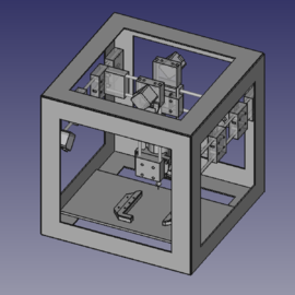
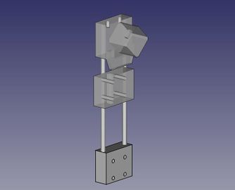
=CAD= | =CAD files= | ||
[[File:d3dcnccm.png|500px]] | |||
*'''Assembly:''' [[File:D3D_Circuit_Mill.fcstd]] | *'''Assembly:''' [[File:D3D_Circuit_Mill.fcstd]] | ||
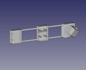
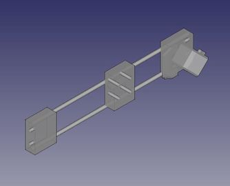
==Simplified Files== | |||
=Simplified | |||
<gallery mode="packed-hover" heights="180"> | <gallery mode="packed-hover" heights="180"> | ||
| Line 57: | Line 237: | ||
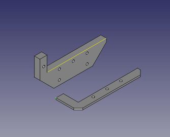
File:D3D_circuit_Mill_Motor_Mount.jpeg|Spindle Motor Mount: [[File:D3D Circuit Mill Motor Mount.fcstd]] | File:D3D_circuit_Mill_Motor_Mount.jpeg|Spindle Motor Mount: [[File:D3D Circuit Mill Motor Mount.fcstd]] | ||
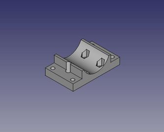
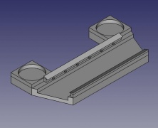
File:PCBholder_image.jpeg|PCB holder: [[File:PCBholder simplified.FCStd]] | |||
</gallery> | |||
==Accurate Files== | |||
<gallery mode="packed-hover" heights="120"> | |||
File:D3D end stop interface complex.jpeg|'''3x End Stop interface:''' [[File:D3D End stop interface.fcstd]] | |||
File:Universal axis carriage side.jpeg|'''16x carriage piece:''' [[http://opensourceecology.org/w/images/archive/9/9b/20170612174329%21Universal_axis_carriage_side.fcstd]] | |||
File:Universal Axis Idler piece short complex.jpeg|'''16x idler piece short:''' [[http://opensourceecology.org/w/images/archive/8/80/20170613014820%21Universal_Axis_Idler_Side_short_version.fcstd]] | |||
File:Universal axis motor side complex.jpeg|'''12x motor piece:''' [[http://opensourceecology.org/w/images/archive/0/08/20170612173557%21Universal_axis_motor_side.fcstd]] | |||
File:D3D_circuit_Mill_Motor_Mount.jpeg|2x Spindle Motor Mount: [[File:D3D Circuit Mill Motor Mount.fcstd]] | |||
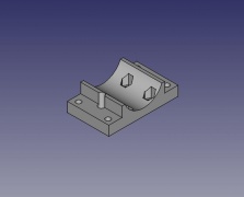
File:PCBholderaccurate.jpeg|PCB holder: [[https://github.com/CarlosGS/Cyclone-PCB-Factory/blob/v2.3/Output_files/Cycl_Ycarriage_PCBholder_x2.stl]] and [[File:D3dcnccm PCB holder.stl]] | |||
</gallery> | </gallery> | ||
= | ==List of Files== | ||
== | |||
*'''Assembly:''' [[File:D3D_Circuit_Mill.fcstd]] | |||
*[[ | *Frame 16" assembled: [[File:Full_Frame_16in.FCStd]] | ||
*Single 16" frame: [[File:Single_Frame_16in.fcstd]] | |||
*Single x axis: [[File:D3D Circuit Mill X Axis.fcstd]] | |||
*Single y axis: [[File:D3D Circuit Mill Y Axis.fcstd]] | |||
*Single z axis: [[File:D3D Circuit Mill Z Axis.fcstd]] | |||
*Spindle Motor: [[File:t-king_spindlemotor.fcstd]] | |||
*Spindle Motor Mount: [[File:D3D Circuit Mill Motor Mount.fcstd]]. STL - [[File:D3D Circuit Mill Motor Mount.stl]] | |||
*''PCB Holder: [[File:d3dcnccm_PCB_holder.stl]] [[File:PCBholder simplified.FCStd]] | |||
= | ==Design Notes== | ||
Note on CAD Procedure and Organization: | |||
#Draw a frame piece, and create a complete frame made of 6 of these pieces. | |||
#Save file: [[File:D3D 13" Frame.fcstd]] | |||
#Begin the design by downloading the X axis - [[File:D3D_16_Sub-assembly_X_Axis.fcstd]] | |||
#Correct the length of the axis to 11" length (for 13" frame - 1" shorter on each side to accommodate mounting on the Y axes). Rotate the axis such that the orientation - when looking according to the Viewing Direction and XYZ axis orientation of Slide 1 in Working Document - is that the motor is on the left side of the axis (note that the orientation shown in First Slide in the Working Document has the motor on the right hand side, which is not correct). | |||
#Save the file as [[File:D3D Circuit Mill X Axis.fcstd]] once the length is 11" and orientation is correct. This will be the file you can use later for the x axis (2 of them) to merge into the final assembly - with the second x axis being a mirror image. | |||
#Now create the Y axis according to the orientation convention of the First Slide in the Working Document. This axis should be 13" long. | |||
#Save the y axis file as [[File:D3D Circuit Mill Y Axis.fcstd]]. | |||
#Now create the Z axis as in the working document. This axis can be 8" long - as we don't need a lot of z travel. | |||
#Save the Z axis file as [[File:D3D Circuit Mill Z Axis.fcstd]]. | |||
#Import the | |||
[[ | =Industry Standards= | ||
*Toner Transfer gets reliable traces down to 0.15 mm, D3D CNC circuit mill works to 0.5 mm traces. [[https://hackaday.com/2016/09/12/take-your-pcbs-from-good-to-great-toner-transfer/]. Disadvantage: a mill can do your holes and cut out your circuit board as well. Advantage - smaller features are possible. | |||
*'''Othermill''' - 0.003 mm positioning, with minimum mill bit of 0.25 mm - [https://support.bantamtools.com/hc/en-us/articles/115001672214?_ga=2.76807957.1055366763.1554638394-1202104997.1554638394]. Positioning accuracy is not the limiting factor for features - but mill bit size. Minimum size is the same for D3D and Othermill (0.25 mm). | |||
*[[https://bitbucket.org/compactpcbmaker/cpcbm The Ant PCB Maker]] | |||
*Hackaday projects - [https://hackaday.io/list/6906-cnc-projects] | |||
*Not open source - LilCNC - [https://www.thingiverse.com/thing:826098]. Uses Easel online 2D design software. | |||
=Existing Open Source Designs= | |||
*[[Cyclone PCB Circuit Mill]] | |||
*[[Sienci Mill]] | |||
[ | =Curriculum= | ||
*Working doc - [https://docs.google.com/presentation/d/1yRAuKGW05AA-JhnLo549PtzlAXDQEtf4T6kICJ3PGJ4/edit#slide=id.g3bc8d1c8b9_0_3] | |||
= | =See Also= | ||
*[[PCB Milling with Marlin]] | |||
*[[Universal CNC Axis]] | |||
*[[Open Source Digital Fabrication Construction Set]] | |||
*[[Open Source Electronics Construction Set]] | |||
=Useful Links= | |||
*Tom's Guide 2018 discussing inferiority of mill conversions - [https://youtu.be/MDz1A1XDOt8] | |||
* | |||
Latest revision as of 22:54, 9 February 2021
Basics
- A CNC mill used for PCB Milling
- Can't make as small of traces as a lithography+ethcing system, BUT it is far cheaper and easier to use (ie no chemical etchants or photoresists needed)
- Uses the D3D Univeral Axis
- D3D circuit mill - https://mi_shell.gitlab.io/models_online/ose_webgl/d3d_circuit_mill.html
Genealogy
- The CNC circuit mill took another turn in 2019 with the Open Source Microfactory STEAM Camp, where we built the D3D Universal 3D printer with a hole-drilling capacity for circuit boards.
- D3D CNC Circuit Mill - built in 2018 with the Universal Axis.
- We also built HydraFabber in 2014 - which used a low cost spindle. See John Log for pictures of the mill. This is prior to the Universal Axis, which was introduced in 2016. The spindle was built and run, but we did not mill any boards.
- Yoonseo Kang built a circuit mill while at OSE in 2012. See Yoonseo Log - as a power user, Yoonseo developed a lot of useful proofs of concept, such as the Cold Saw and Tooling Plate, among others. Specifically - v1 was built, and v2 was not. These were pre-Universal Axis.
3D Model
- You can rotate, zoom, and explode:
![]() Hint: July 2018 - OSE Germany is working on a version of their MPPT Solar Charge Controller which can be milled with the OSE D3D CNC Circuit Mill - https://github.com/LibreSolar/MPPT-Charger_20A/issues/28
Hint: July 2018 - OSE Germany is working on a version of their MPPT Solar Charge Controller which can be milled with the OSE D3D CNC Circuit Mill - https://github.com/LibreSolar/MPPT-Charger_20A/issues/28
Publication
Published in Inventions, http://mdpi.com/2411-5134/3/3/64
Preprint - https://www.preprints.org/manuscript/201808.0233/v1
Build Instructions
- Drill frame
- Do Cut List below - rods, belt
- Cut bed plate
- Assemble electronics mounting plate
- Assemble spindle in holder
- Test electronics - motion
- Test calibration code
- Run a milling job
Cut List
(400, 350, and 300 lengths would work)
- Belt - x - [2] 29"
- Belt - y - [2] 33"
- Belt - z - [2] 23"
- Rods - x - [4] 14"- = 56"
- Rods - y - [4] 16"- = 64"
- Rods - z - [4] 11" = 44"
- Frame if welded from flats - [24] 1/8"x1"x15" flats -
- Electronics mounting panel - 1/10" plexiglass - 8"x16"
Rods if Using 6' Stock
Try 1
- If use 6 foot stock- 72" - 4x11=44 + 28 = 72.
- 4x16 = 64 (8 left over). It's useful to rework design to allow for 8" rod on Z
- 2x14 = 28 (44 left over)
- 3 rods needed for 162" = 13.5'
Try 2
- 4x14 + 16 => perfect.
- 3x16 + 2x11 = 70 for 2" left over- great.
- 2x11 = 22 with 50 left over. Nice.
Continuing:
- 3x16= 2" left over from last one.
- 4x14 + 16 => perfect
- 1x16+4x11 = 60 - 12 left over.
Italic text
July 2017


Comparison to Industry Standards

Notes: precision is not defined here. If it is positioning accuracy, Othermill appears to be 0.003 (see D3D_CNC_Circuit_Mill#Industry Standards.
BOM
Other Supplies
Single Sided Copper Clad Laminate PCB Circuit Board 4X3 (50pcs) Paramount CCL Link: http://a.co/3YcKSBe
Xuchuan 10Pcs PCB Print Circuit Board Carbide Micro Drill Bits 0.3-1.2mm Xuchuan Link: http://a.co/0KviIvf
JIUWU 1.0mm Tungsten Steel Carbide PCB CNC End Mill Engraving Bits Milling Machine Pack of 10 by JIUWU Link: http://a.co/1CL0H32
You can try these tools out - they are inexpensive and may yield good results for milling traces. But if you run into issues, the tools are likely chipping Autek 10x Titanium Coated Carbide PCB Engraving CNC Bit Router Tool 30 Degree 0.1mm Tip(J3.3001Tix10) by Autek Link: http://a.co/6UR8F9T
Instead it may be good to opt for higher quality milling tools. They should last a good long while:
	Universal Milling Tools
	100% Carbide universal milling tool for milling printed circuit board isolation tracks. V-shaped profile for variable milling width. 1.42" (36 mm) overall length.
https://www.lpkfusa.com/Store/pages/ProductDetail.aspx?cat=11%2f42&cid=42&pid=30
All Industrial Tool Supply TR72020 Dial Indicator (Magnetic Base and Point Precision Inspection Set), 1 Pack by All Industrial Tool Supply Link: http://a.co/5EgkHa0
Software: See this link - it has all of the software we used and then some: http://opencircuitinstitute.org/content/software
Additionally here is my web-based leveling utility: http://voltfolio.com/utilities/levelgcode.html
https://www.lpkfusa.com/Store/pages/ProductDetail.aspx?cat=11%2f38&cid=38&pid=76
Sorry I must make one amendment - I linked the incorrect milling tools from LPKF. Here are the correct ones:
https://www.lpkfusa.com/Store/pages/ProductDetail.aspx?cat=11%2f38&cid=38&pid=76
vBOM
Visual BOM:
Calculations
Sources
- File:Backlash Pattern.odg - editable drawing of backlash pattern.
Electronics
Source
- Diagram in Libre Office - File:D3D Circuit Diagram.odg
Photo Album
- On google photos - [5]
Videos
- Mill Experiment - Backlash Compensation Stress Test - [6]
- Leveled circuit - holder slides at the end - [7]
- Mill Experiment - Large Leveled Circuit Take 2 - [8]
- Auto Probing Experiment - [9]
- Stepper driver breakout board - [10]
Workshop Preparation
Development Template
Burndown
Feb 2018 Update
September 2017 Update
Development Pictures

The disassembled axes required to convert the D3D printer to the circuit board mill

These are the required additional parts to transition from the 3D printer to the circuit board mill

The complete set of axes for the D3D circuit mill
Working Document
Design
Data Collection
CAD files

- Assembly: File:D3D Circuit Mill.fcstd
Simplified Files
Assembly: File:D3D Circuit Mill.fcstd
D3D frame 16": File:D3D frame assembled 16 inch.FCStd
Single x axis: File:D3D Circuit Mill X Axis.fcstd
Single y axis: File:D3D Circuit Mill Y Axis.fcstd
Single z axis: File:D3D Circuit Mill Z Axis.fcstd
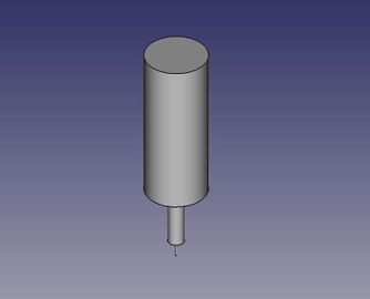
spindle motor: File:T-king spindlemotor.fcstd
Spindle Motor Mount: File:D3D Circuit Mill Motor Mount.fcstd
PCB holder: File:PCBholder simplified.FCStd


Accurate Files
3x End Stop interface: File:D3D End stop interface.fcstd
![16x carriage piece: [[1]]](/images/thumb/6/65/Universal_axis_carriage_side.jpeg/216px-Universal_axis_carriage_side.jpeg)
16x carriage piece: [[1]]
![16x idler piece short: [[2]]](/images/thumb/d/d4/Universal_Axis_Idler_piece_short_complex.jpeg/222px-Universal_Axis_Idler_piece_short_complex.jpeg)
16x idler piece short: [[2]]
![12x motor piece: [[3]]](/images/thumb/9/91/Universal_axis_motor_side_complex.jpeg/216px-Universal_axis_motor_side_complex.jpeg)
12x motor piece: [[3]]
2x Spindle Motor Mount: File:D3D Circuit Mill Motor Mount.fcstd
![PCB holder: [[4]] and File:D3dcnccm PCB holder.stl](/images/thumb/6/6d/PCBholderaccurate.jpeg/229px-PCBholderaccurate.jpeg)
PCB holder: [[4]] and File:D3dcnccm PCB holder.stl

![16x carriage piece: [[1]]](/wiki/File:Universal_axis_carriage_side.jpeg)
![16x idler piece short: [[2]]](/wiki/File:Universal_Axis_Idler_piece_short_complex.jpeg)
![12x motor piece: [[3]]](/wiki/File:Universal_axis_motor_side_complex.jpeg)
![PCB holder: [[4]] and File:D3dcnccm PCB holder.stl](/wiki/File:PCBholderaccurate.jpeg)
List of Files
- Assembly: File:D3D Circuit Mill.fcstd
- Frame 16" assembled: File:Full Frame 16in.FCStd
- Single 16" frame: File:Single Frame 16in.fcstd
- Single x axis: File:D3D Circuit Mill X Axis.fcstd
- Single y axis: File:D3D Circuit Mill Y Axis.fcstd
- Single z axis: File:D3D Circuit Mill Z Axis.fcstd
- Spindle Motor: File:T-king spindlemotor.fcstd
- Spindle Motor Mount: File:D3D Circuit Mill Motor Mount.fcstd. STL - File:D3D Circuit Mill Motor Mount.stl
- PCB Holder: File:D3dcnccm PCB holder.stl File:PCBholder simplified.FCStd
Design Notes
Note on CAD Procedure and Organization:
- Draw a frame piece, and create a complete frame made of 6 of these pieces.
- Save file: File:D3D 13" Frame.fcstd
- Begin the design by downloading the X axis - File:D3D 16 Sub-assembly X Axis.fcstd
- Correct the length of the axis to 11" length (for 13" frame - 1" shorter on each side to accommodate mounting on the Y axes). Rotate the axis such that the orientation - when looking according to the Viewing Direction and XYZ axis orientation of Slide 1 in Working Document - is that the motor is on the left side of the axis (note that the orientation shown in First Slide in the Working Document has the motor on the right hand side, which is not correct).
- Save the file as File:D3D Circuit Mill X Axis.fcstd once the length is 11" and orientation is correct. This will be the file you can use later for the x axis (2 of them) to merge into the final assembly - with the second x axis being a mirror image.
- Now create the Y axis according to the orientation convention of the First Slide in the Working Document. This axis should be 13" long.
- Save the y axis file as File:D3D Circuit Mill Y Axis.fcstd.
- Now create the Z axis as in the working document. This axis can be 8" long - as we don't need a lot of z travel.
- Save the Z axis file as File:D3D Circuit Mill Z Axis.fcstd.
- Import the
Industry Standards
- Toner Transfer gets reliable traces down to 0.15 mm, D3D CNC circuit mill works to 0.5 mm traces. [[11]. Disadvantage: a mill can do your holes and cut out your circuit board as well. Advantage - smaller features are possible.
- Othermill - 0.003 mm positioning, with minimum mill bit of 0.25 mm - [12]. Positioning accuracy is not the limiting factor for features - but mill bit size. Minimum size is the same for D3D and Othermill (0.25 mm).
- [The Ant PCB Maker]
- Hackaday projects - [13]
- Not open source - LilCNC - [14]. Uses Easel online 2D design software.
Existing Open Source Designs
Curriculum
- Working doc - [15]
See Also
- PCB Milling with Marlin
- Universal CNC Axis
- Open Source Digital Fabrication Construction Set
- Open Source Electronics Construction Set
Useful Links
- Tom's Guide 2018 discussing inferiority of mill conversions - [16]