Aidan Williamson Log: Difference between revisions

From Open Source Ecology
Jump to navigation Jump to search
 
(149 intermediate revisions by 2 users not shown)
Line 1: Line 1:
[[Special:Contributions/Aidan_Williamson|contribs]]<br/>
{{RightTOC}}
 
{|
|-
|[[Special:Contributions/Aidan_Williamson|contribs]]<br/>
 
 
Old Logs:
Old Logs:
*[[Aidan_Williamson_Log_2018-2020]]
*[[Aidan_Williamson_Log_2015-2017]]
*[[Aidan_Williamson_Log_2014]]
*[[Aidan_Williamson_Log_2013]]
*[[Aidan_Williamson_Log_2012]]
*[[Aidan_Williamson_Log_2012]]  
 
=July 17, 2019=
Don't have edit access on [[Soil Mixer 2019|Soil Mixer Design Doc]] so I'll record my thoughts here:
#What propels the stabilized soil mixture out of the hammermill?
#Relying on gravity and ratio of areas to dose quantities of soil and earth. This, in my opinion, will be irregular. You would have to be able to change the size of the stabilizer aperture in the field.
##Based on pH for lime. Do a sample every so often
##Based on color for cement?
#The raw soil would need to be crushed and dried before it will fall into the drawer in a repeatable way. This kind of defeats the purpose of a hammermill.
##I could see this propagating the error we have in block size throughout the system. Relying on the soil to fall into a hole the same way each time. Might double the error, right? Double the random uncertainty in block size. Or give a systematic shifts in error during a shift or certain working condition.
#An auger system could meter the input of soil and stabilizer in a more controlled way while still using only one actuator (motor instead of cylinder - though maybe it works out to an extra motor). A variable pulley could be used to set the stabilizer ratio. [https://www.mcmaster.com/pulleys This is an off-shelf item.]
##[https://www.youtube.com/watch?v=O4h-Me5lSOY Example of variable speed pulley system.] If we use the same auger size for soil and stabilizer, then gear reduce the stabillizer auger to give 3% to 10% the speed of the soil auger. If you need more than 10% stabilizer then you are using a very low clay content soil and using a ton of cement - rethink the soil blend and if you need to, buy a different pulley. 
 
=July 16, 2019=
Tried to go to the dev meeting to discuss soil mixer per discussion with Marcin last week but nobody was there save an AFK Abe.
 
Need feedback on workshop tools and infrastructure list at [[Belize CEB]]. I'm not including any hardware or materials for the house - just the tools that are required to build it. Just working from what I can imagine would be necessary. Another more experienced set of eyes would be good to glance over what I have listed so far.
 
Thinking about soil prep: for Marcin's hammermill concept, how do we get dirt at OMC (optimum moisture content) before it goes into the hammermill? One way could be to figure out OMC by volume of dry dirt, volume of water and have laborers fill 5 gallon buckets with dry, screened dirt and add water from another bucket with demarcated OMC line. This unmixed bucket of water and dirt goes in to hammermill. Assume that the dirt has (non-uniformly) absorbed the water AND that the hammermill will actually give a homogeneous mix. I don't see why the hammermill would give a homogenous mix unless you cap the mixing chamber to prevent material escaping before a homogeneous mix is obtained. This would take longer than a press cycle so it would have to mix more than 1 block's worth per round.
 
=July 11, 2019=
[[Mader's Machine]]
 
=July 5, 2019=
CADded [[2" Universal Axis|D3D Mill assembly]] in 2 days
 
=June 20, 2019=
<html><iframe width="560" height="315" src="https://www.youtube.com/embed/FJvYA0GuFOc" frameborder="0" allow="accelerometer; autoplay; encrypted-media; gyroscope; picture-in-picture" allowfullscreen></iframe></html>
 
=June 16, 2019=
[[File:Taper_to_Straight_adapter.fcstd]] [[File:Taper_to_Straight_Adapter_Wheel_Hub.fcstd]]<br/>
<html><iframe width="1000" height="600" src="https://scrumy.com/FeF_STEAM" frameborder="0" allowfullscreen></iframe></html>
 
=Feb 25, 2019=
I made a new tube builder when I heard mine wasn't working in FreeCad 0.16 on Ubuntu.<br/>
The new file is based on the Sketcher, Draft, and Part workbenches whereas the original file was based on the Sketcher and Part Design workbenches.
 
[[File:Alternative_Universal_Tube_Builder.fcstd]]
 
Here is a video explaining the new file approach
<br/>
<html><iframe width="560" height="315" src="https://www.youtube.com/embed/PcCe6sOE3pc" frameborder="0" allow="accelerometer; autoplay; encrypted-media; gyroscope; picture-in-picture" allowfullscreen></iframe></html>
 
=Feb 23, 2019=
Video showing making of a spreadsheet parametrized cad file.<br/>
<html><iframe width="560" height="315" src="https://www.youtube.com/embed/camIgIfUjss" frameborder="0" allow="accelerometer; autoplay; encrypted-media; gyroscope; picture-in-picture" allowfullscreen></iframe></html>
 
=Feb 22, 2019=
Made a video about the tube generator and improved the file by adding HoleSpacing parameter to spreadsheet.
<html><iframe width="560" height="315" src="https://www.youtube.com/embed/HKxSg1iWeLU" frameborder="0" allow="accelerometer; autoplay; encrypted-media; gyroscope; picture-in-picture" allowfullscreen></iframe></html>
 
=Nov 20, 2018=
 
Here is a version uploaded to the OSE Wiki. It should work but may have design flaws. I'm using an O-ring to seal the cylinder in the cap trepan groove. This is questionable.
<br/>
[[File:Universal_Cylinder_Builder_ADW.FCStd]]
<br/>
<html><iframe width="560" height="315" src="https://www.youtube.com/embed/VoLDv17Tq7o" frameborder="0" allow="accelerometer; autoplay; encrypted-media; gyroscope; picture-in-picture" allowfullscreen></iframe><iframe width="560" height="315" src="https://www.youtube.com/embed/n_ZFx_YQh7w" frameborder="0" allow="accelerometer; autoplay; encrypted-media; gyroscope; picture-in-picture" allowfullscreen></iframe></html>
-----
I've been working on a cad file for the [[CEB_Cylinder|Open Source Cylinder]]. Here is a link to the alpha stage of the file. [https://www.dropbox.com/s/npj8me9f7l0znqp/Universal%20Cylinder%20alpha.FCStd?dl=0 DROPBOX] The end-caps are square with a trepan machined for the tube to seat. The caps could potentially be parted so that a welding operation replaces a machining operation for the tube seat. The Rod is welded to the Piston in my version.
 
Like the universal tube builder, I'm trying to make it parameterized from a spreadsheet. Here is what the parameters look like right now:
 
Name Input (Inches) Output (mm) Note
Cap Side Length 4 50.8
Cap Thickness 1 25.4
Tube OD 3 38.1
Tube Wall Thickness 0.25 6.35
Piston Thickness 1 25.4
Piston Seal Inner, Height 0.3125 7.9375
Piston Seal Inner, ID 2.125 26.9875
Piston Seal Inner, OD 2.5 31.75
Piston Seal Outer, Height 0.25 6.35
Piston Seal Outer, ID 2.125 26.9875
Piston Seal Outer, OD 2.5 31.75
Stroke 12 304.8
Rod OD 1.5 19.05
Rod Stickout 2.5 63.5
Cap Seal Outer, Height 0.25 6.35
Cap Seal Outer, OD 2 25.4
Cap Seal Outer, ID 1.495 18.9865
Cap Seal Inner, Height 0.25 6.35
Cap Seal Inner, OD 2 25.4
Cap Seal Inner, ID 1.495 18.9865
 
Need to add a few parameters like tie-rod diameter. I think the model may need to be scrapped. Especially if one looks at the dependency graph lol. I didn't take as intentional an approach to modeling it as I could have.
 
I believe it is a worthwhile effort, though. A user could generate the CAD for a cylinder of different sizes by simply entering data into a spreadsheet.
 
<br/><html><img src="https://www.dropbox.com/s/5fs1vqief8zlzar/1111%25200020%2520-%252012393%2520w%2520-%2520EN_tcm_12-146081.png?dl=1"></img></html><br/>[[File:UCB_Alpha.png|750px|Left]]
 
==Notes==
The caps as I have drawn can be easily made on a lathe and mill.
How i would make this:
Cut the plate to size and machine square. Surface grind for extra credit. Put the four tie rod holes in but make them half inch reams. Using shoulder bolts, attach the plate to a lathe jig or 2 bolts and 2 dowel pins. To make the lathe jig, press fit a piece of 4" or similar crs into a thick plate with the bolt pattern on it and weld. Face the jig on the lathe after welding. The bolt pattern should be put in after the welding operation. Use custom vise jaws and maybe a small bore for picking up the center. For the rod end cap, drill and bore the rod hole then bore internal grooves. Then cut trepan groove. For the base, it's just a trepan.
Make those in half a day including making the jig.
 
As an alternative, I was imagining "slicing" the caps into layers, like 3d printing, and then welding the slices together.
 
For plastic cylinders, I would start with pvc or abs pipe as the tube. I'd go down that road before I started messing with a metal prototype.
 
I'll keep thinking about it.


|| <html><iframe width="600" height="500" src="https://osedev.org/wiki/Aidan?start=9/1/2019"></iframe></html>
|}


Aidan


=Nov 5, 2018=
=December 12, 2022=
Here is a file that might be helpful for y'all. Open the Universal Tube Builder file and use the spreadsheet to create tubing with all dimensions parametrized. Holes will automatically be set to 4" spacing. I can change that if you want. You can define the standoff for the first hole.  
All the exterior module [[seh4cad|Cheatsheets]] I've been uploading are looking at the module from the exterior of the building which may be confusing when it's time to install electrical boxes. Probably will just stick with the scheme for the first floor and start drawing the cheatsheets from the interior for the 2nd floor.


[[File:Universal_Tube_Builder_ADW.FCstd]]
=July 20, 2021=
[[Hydraulic DCV Comparison]]


[https://www.freecadweb.org/wiki/Expressions FreeCAD expressions for constraint solver]
Scalable CEB Circuit. Up to 3 PowerCubes with hydraforce part. GPM numbers assume 30gpm pump. Pump can be replaced with intake manifold. Scale to 3 powercubes input. Quick disconnect one and put it on tractor. Put it back. etc.
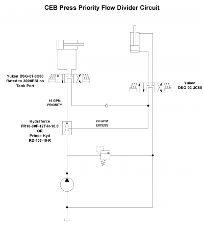
[[File:CEB_Prince_400.png|400px]]


[[Category:Logs]]
[[Category:Logs]]

Latest revision as of 00:58, 3 December 2022

contribs


Old Logs:


December 12, 2022

All the exterior module Cheatsheets I've been uploading are looking at the module from the exterior of the building which may be confusing when it's time to install electrical boxes. Probably will just stick with the scheme for the first floor and start drawing the cheatsheets from the interior for the 2nd floor.

July 20, 2021

Hydraulic DCV Comparison

Scalable CEB Circuit. Up to 3 PowerCubes with hydraforce part. GPM numbers assume 30gpm pump. Pump can be replaced with intake manifold. Scale to 3 powercubes input. Quick disconnect one and put it on tractor. Put it back. etc.

CEB Prince 400.png