Aidan Williamson Log 2018-2020
contribs
Old Logs: |
May 28, 2020
Here are some documents that I prepared for the crew in Belize:
And here is the updated, final version of the code uploaded to the controller. The issue with the machine jumping around the code was fixed either with that code update or by replacing a broken flyback diode on the drawer cylinder - I'm not sure which one was the problem. But it runs well now.
File:Controller v19.01Belize Final.zip
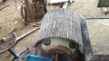
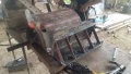
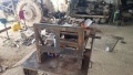
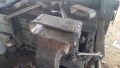
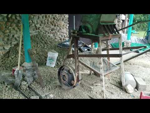
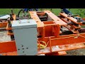
After the workshop, sometime in March, I visited the man with the Brazilian CEB Production Machinery lineup and assessed its value. Each machine appears to be capable of being restored and some of them work well already.
A photo album with pictures of the machines is here: Google Photos
The toolchain goes like this:
- Raw soil is crushed with a coffee-grinder type crusher
- Soil and cement are loaded into their own dosers
- These dosers add material to a conveyor belt at metered rates set by operator
- The dry materials enter the barrel-type mixer through an opening at the end of the conveyor with water spraying from above
- The mixer ouput drops onto another conveyor
- This conveyor drops into the CEB press
The spreadsheet linked to above estimates the cost to produce block using this equipment lineup.
I decided to leave Belize at the end of April and have basically been in transit or preparing for the trip since then so I'm long overdue in uploading these materials but better late then never. I plan on finalizing the Production Handbook eventually.
February 27,2020
http://img.youtube.com/vi/OqV2SaLImlQ/0.jpg
February 24,2020
Showed some of the workshop participants how to install drawer onto CEB press. Replaxed powercube coupler. Forklift did not show up to move press. Will try to demo press tomorrow.
Updateed BOM. Incomplete
January 28, 2020 - February 16, 2020
Took apart controller and discovered possible grounding issue in usual usb port case location. Reassembled and issue has yet to strike again.
Reassembled Ceb press with primary arms parallel to press chamber. Press chamber side plates being awfully out of square (due to chamber sides bring totally out of square) causes this to be a slow process. I believe an issue with the way the chanmber was welded causes the blocks to delaminate during ejection because the chamber cross section shrinks as the blocks go up. I tried correcting this issue with shims. The outcome of this shim modification is unknown due to the powercube coupler failure. Loose motor mount bolts caused the hard pump shaft to grind away the softer coupler's splines. Machine has been down since February 3.
I had gotten the nylon blocks bored out to press fit bushings in since the bore was fully worn out on all 4 bushings. Grinded off old bushing alignment angle corner pieces and welded new ones on. Also dropped the drawer lift stop plates to 1/32" clearance. This was done before coupler failure.
Delivered blocks to copper bank.
January 27, 2020
Automode issue persists. I now suspect hardware. Will try some more debugging later.
Random CEB thoughts:
- 728psi - maximum pressure we are pressing our blocks with. I think it's too low for the high clay soil we are using here. 2700psi fluid pressure, 5" cylinder, 6x12.125in press plate. I'd love to try a larger cylinder.
- High clay soils are very moisture sensitive. If we vary by ~3% then we make bad blocks
- Im going to cut open the drawer and work on the guide rail system soon. It needs an overhaul for this machine to stand a chance as a production unit.
- After pressing 3k blocks the main chamber spread itself on its oversized bolt holes and i need to re shim the press foot. Recommend making the bolt holes with less tolerance.
January 26, 2020
Will try to upload vids today cause its a 3X DATA SUNDAY WOOHOOOO
Changed out the pressure gauge on the valve manifold. Old one somehow bent its needle, wasn't reading right, and was leaking. New one seems to be of superior quality.
Debugged automode in code on block press. Fixed the issue. Working code: File:BelizeCEBFirmware19.11.zip
See below for debugging I did:
Issue with CEB press:
Autostate Changed To:
0
Autostate Changed To:
1
Loading Soil.
Selector Poisition:
4
Drawer Move Time:1651
Drop Time Calculated:2529
Autostate Changed To:
2
Mid Point Sensor Triggered
Autostate Changed To:
3
Block Pressed. Lowering Block
Block Lowered.
Autostate Changed To:
4
Autostate Changed To:
5
Autostate Changed To:
0
Autostate Changed To:
1
Loading Soil.
Selector Poisition:
4
Drawer Move Time:1649
Drop Time Calculated:2526
Autostate Changed To:
2
Mid Point Sensor Triggered
Autostate Changed To:
3
Bloc⸮Auto Mode Enabled
Autost⸮Auto Mode Enabled
Autostate Changed To:
1
Loading Soil.
Selector Poisition:
4
Drawer Move Time:3
Drop Time Calculated:4
Autostate Changed To:
2
Mid Point Timing Interrupt
Autostate Changed To:
3
Block Pressed. Lowering Block
Block Lowered.
Autostate Changed To:
4
Autostate Changed To:
5
The issue is in the middle of the chunk of serial communications above:
Autostate Changed To:
3
Bloc⸮Auto Mode Enabled
Autost⸮Auto Mode Enabled
Autostate Changed To:
1
Appears to be an issue with dropping out of automode, not running the terminateAutoExec() function and picking back up at state 1 instead of 3. I thought maybe it was an issue with serial communicatoins being on without a laptop connected but i was able to get it to happen with the laptop connected and the serial monitor on.
It doesn't seem to happen without dirt in the machine though I have not tested this extensively cuz I don't wanna waste gas.
It doesn't happen when I knock the controller box so I don't suspect a wiring issue. Automode switch input works fine when I wiggle the wire.
Found it! It's the midpoint timing interrupt - or that's at least one of the issues.
High Pressure!
High Pressure!
Auto Mode Enabled
Autostate Changed To:1
Loading Soil.
Selector Poisition:4
Drawer Move Time:1695
Drop Time Calculated:2596
Autos⸮Auto Mode Enabled
Autostate Changed To:1
Loading Soil.
Selector Poisition:4
Drawer Move Time:3
Drop Time Calculated:4
Autostate Changed To:2
Mid Point Timing Interrupt
Autostate Changed To:3
Block Pressed. Lowering Block
Block Lowered.
Autostate Changed To:4
Autostate Changed To:5
Autostate Changed To:0
Autostate Changed To:1
Loading Soil.
Selector Poisition:4
Drawer Move Time:1658
Drop Time Calculated:2539
Autostate Changed To:2
Mid Point Sensor Triggered
Autostate Changed To:3
Block Pressed. Lowering Block
Block Lowered.
Autostate Changed To:4
Autostate Changed To:5
Autostate Changed To:0
Autostate Changed To:1
Loading Soil.
Selector Poisition:4
Drawer Move Time:1652
Drop Time Calculated:2530
Autostate Changed To:2
Mid Point Sensor Triggered
Autostate Changed To:3
Block Pressed. Lowering Block
Block Lowered.
Autostate Changed To:4
Autostate Changed To:5
Autostate Changed To:0
Autostate Changed To:1
Loading Soil.
Selector Poisition:4
Drawer Move Time:1655
Drop Time Calculated:2535
Autostate Changed To:2
Mid Point Sensor Triggered
Autostate Changed To:3
Block Pressed. Lowering Block
Block Lowered.
Autostate Changed To:4
Autostate Changed To:5
Autostate Changed To:0
Autostate Changed To:1
Loading Soil.
Selector Poisition:4
Drawer Move Time:1655
Drop Time Calculated:2535
Autostate Changed To:2
Mid Point Sensor Triggered
Autostate Changed To:3
Block Pressed. Lowering Block
Block Lowered.
Autostate Changed To:4
Autostate Changed To:5
Autostate Changed To:0
Autostate Changed To:1
Loading Soil.
Selector Poisition:4
Drawer Move Time:1652
Drop Time Calculated:2530
Autostate Changed To:2
Mid Point Sensor Triggered
Autostate Changed To:3
Block Pressed. Lowering Block
Block Lowered.
Autostate Changed To:4
Autostate Changed To:5
Autostate Changed To:0
Autostate Changed To:1
Loading Soil.
Selector Poisition:4
Drawer Move Time:1652
Drop Time Calculated:2530
Autostate Changed To:2
Mid Point Sensor Triggered
Autostate Changed To:3
Block Pressed. Lowering Block
Block Lowered.
Autostate Changed To:4
Autostate Changed To:5
Autostate Changed To:0
Autost⸮Auto Mode Enabled
Autostate Changed To:1
Loading Soil.
Selector Poisition:4
Drawer Move Time:3
Drop Time Calculated:4
Autostate Changed To:2
Mid Point Timing Interrupt
Autostate Changed To:3
Block Pressed. Lowering Block
Block Lowered.
Autostate Changed To:4
Autostate Changed To:5
Autostate Changed To:0
Autostate Changed To:1
Loading Soil.
Selector Poisition:4
Drawer Move Time:1658
Drop Time Calculated:2539
Autostate Changed To:2
Mid Point Timing Interrupt
Autostate Changed To:3
Auto Mode Disabled
Autostate Changed To:0
All Solenoids Off
I know that's a longish log but there appears to be 2 issues:
- Mid point timing interrupt coming on immediately. This must be a data type issue. It really should only come on if we blow by the mid point sensor. It's coming on while we are still extended, though.
- Automode coming on and off or coming on after never being off while mid cycle. Some lines abruptly switch to "automode enabled".
Now me t'inkin that the mid point timing interrupt is actually due to the automode on/off thing. Drawer move time is at 3 in the above block of code after a automode issue artifact. Need to find out why automode is dropping off.
I tried switching the input pin for switchAUTO but that did not help.
Ok I think i got it f'real. Added !automode condition to if statement when we turn automode on. I think I was writing automode on when it was already on which lead to the issue. Appears to work guud now.
January 22, 2020
Worked on cad of house. Updated to reflect Belize Build Concepts doc and last conversation. Left a gap between the front windows. Wood list is incomplete waiting on roofing and loft framing detail.

January 21, 2020
Numbers on labor are in. I wanted to wait until we finished all the clay from the first round of crushing before I reported numbers.
We made ~1500 block (50 unstabilized) and spent $1050 USD over the course of 11 days. This translates to $0.76 USD per block. Conditions were exceedingly poor in the first 8 or so days of the work: soil piles were very wet, rain came frequently, canal was not in place which meant work area was muddy, dry dirt would get splashed from heavy rains. My team is smarter and works more efficiently now that they have seen the entire process. The rain is only a brief shower or two per day now and the sun has been good to us. We are back down to a 5-6 man crew until we have enough crushed clay to press block again. Hopefully by Saturday. The crusher is running very quickly with the superbly dry clay that we have right now.
I'm seeing the shortcomings of Ram Farm Sand.
- Price: it was not as cheap as I thought it would be. I believe he charged us roughly the same as a delivery of commercially available sand from the quarry. A miscommunication lead me to believe it would be cheap material.
- Silt: It's a very silty sand and this silt seems to almost be springy. The silt is very chalky which takes away from the strength of the blocks. Typically the cross section where the blocks fail in the jig is across a combination of these lumps.
- Sharpness of particles: From the beginning they had higher sphericity than desired - though better than the builders' sand commercially available. Edges are jagged and sharp but sphericity is medium. If only I could find the sub-angular sand that the quarry in Birdsboro, PA sold me for my casting bench in 2014...
- Large silt lumps: means we have to filter the sand through a 1/4" screen. This costs labor and since the sand is wet it costs even more labor. This in particular is killing us on block cost.
I have already gotten the green light from Scott to invest in another type of sand - quarry dust. It should requires no filtration. This will save us money in the long run. Larger gravel particles should not be an issue. We may have to screen it though the 3/8" expanded metal screen but that will take way less time than the filtration of wet silty sand through 1/4" screen which requires trowels and 2-3 workers.
The sand cost was $275/ load. For quarry dust the price is $312/ load but it should require little to no processing labor. We spent about 35 cents per bucket of sand to process. Not good.
I believe we can get down to ~$0.50/ block if we have: dry conditions and better sand.
Now that the soil mixer is nixed I think the way forward for Ram/Scott is to keep looking for more suitable material that requires less processing and to price out the cost of fabricating a planetary or drum hammermill type mixer operated by 2-3 men. 1 skilled and 3 unskilled to press ~1000 block per day could cost as low as 10-20 cents per block in labor and power. The pursuit of the OSE prototype soil mixer doesn't make economic sense at this stage in its design. It would have to be a labor of love - a value judgement based on an activist's integrated concept of value.
January 19, 2020
The drawer valve spool was dirty and didn't move freely in the valve block. The block shows signs of wear on the landings in the valve block. I cleaned it by bathing it in hydraulic fluid in a ziploc bag and large black particles flowed out. Didn't look like metal. The spool itself looks good. It seems like there's a burr on one of the landings.
I swapped the eaton valve in and it runs fine. One of the eaton valves didn't work in one direction. So we have no working backup valve. I'll take the valves to Heinrich to see what he can do with them. Maybe clean them, maybe hone the block on the power valve usa one.
In the end I put the motor spool valve with pilot-op check valve on the drawer and put the eaton one on the press cylinder. Need to move the midpoint sensor because the two valves, though interchangeable, are from different manufacturers and behave slightly differently.


Also capped off a leak on the power cube that I believe is responsible for a loss of ~1/8 tank.
Here is a playlist for each day so far. I try to make a video after each day. They are not always super informative.
January 13-18, 2020
We worked from 7AM-3:30PM Monday to Saturday this week. Tarps and canal are keeping the work area dry enough to proceed. Crew crushed soil from Monday to Thursday and then pressed block Friday and Saturday. M-F we had 5 workers and Saturday we had 9.
The sand pile is saturated with water which is good and bad. It's bad because it takes longer to filter the sand through the 1/4" mesh. It's good because we already have moisture distributed evenly through the mix when we blend so we have to add less water. The mixing of the water is the most difficult part of the mixing process. I set up a water pump to use a misting hose sprayer but it is slow and the crew prefers to add water with their hands from a bucket. For unstabilized block we don't need to add any water.
They are an unbelievably great team. Very positive attitudes, wanting to succeed, wanting to improve, wanting to do a good job. I couldn't ask for a better attitude. They improved the pendulum crusher with a studded static plate insert and wind block, and came up with a great workflow to improve crusher output.
We started production by making 1 batch (50 blocks) of unstabilized. I didn't want to use cement on their first try. The first round didn't require adding any water as the moisture content of the sand was sufficient which was really quite great. When we switched to 8% cement it required adding more water.
My batches are based on 1 bag of cement. Here's how I calculate my batch sizes:
- Determine stabilization percentage. Example: 8%
- Determine soil/sand ratio. Example: 1:1
- Find cement bag mass. Example: 94.5lbs
- Calculate total batch mass:
- 94.5lbs = 0.08(Total Batch Mass)
- Total Batch Mass = 1181 lbs
- Calculate mass of soil/sand.
- Total Batch Mass - Cement Mass
- 1181 lbs - 94.5lbs = 1086 lbs
- Calculate mass of soil and sand
- 1086 lbs at 1:1 ratio is 543 lbs each soil and sand
- Determine mass of measuring device. Example: wheelbarrow
- 1 wheelbarrow is 4.5 buckets of volume
- 1 bucket of our soil is 60lbs
- 1 bucket of wet sand is 60lbs
- 1 wheelbarrow is 270lbs of soil or wet sand
- Determine number of measuring device per batch:
- Soil Mass = 543lbs = two 270lb wheelbarrows
- same for our wet sand.
So a batch is 2 wheelbarrows of each soil and sand and 1 sack of cement for 8% stabilized blocks.
To find out how many blocks this will theoretically yield, divide total batch mass by mass of one block - 21 lbs for 4" blocks with this recipe. 1181 lbs / 21 lbs = 56 blocks theoretical output.
In practice, since our sand is wet and our crushed clay is expensive we do less than 1 wheelbarrow of clay and more than 1 wheelbarrow of sand.
Now that I have 600 blocks at 8% stabilization I want to try some 5% stabilized blocks which apparently are all the rage in India.
One CEB Press related note: the block heights for a given setting will change depending on cement content. I think a potentiometer is in order (like there used to be) because busting a laptop out and flashing the program with a new value isn't the kind of thing the average Belizean block press operator is going to do.
On Saturday, after 6hrs of pressing blocks the drawer solenoid valve started to fail. I'm not sure if it's got some crap in it or if it's an issue with the valve itself. Wiring looks good. The coils on the valve at issue are giving 5ohms each which appears to be good. It may be silt lock or something else. I'm going to troubleshoot it today (Sunday) so that we don't have down time on Monday.
January 11, 2020
Tarp town vastly improved with bush sticks.
Intermittent rain means that I have to keep my dirt covered with tarps and uncover it for brief periods hoping for sunshine. Weather should clear up when the Cabañuelas is over. LOL
High humidity means "dry" dirt is still sticky. We occasionally get 100%dry dirt and that crushes very quickly. Day 3 of crushing had higher output because of this.
We're still hovering around $0.67 per block. Doesn't include labor for spreading wet dirt, collecting dry dirt, and building tarp town.
http://img.youtube.com/vi/Lr9IeLuRqJQ/0.jpg
It's tempting to ask Question: Why not just use a tractor and rototiller to crush and mix the soil in 1 step?
Answer: We have wet material. You cannot blend sand with wet clay without massive amounts of horsepower and fuel usage - and you get a shitty end result. A tractor rental runs around $100US per day without fuel and without a tiller. So for $200 per day we could maybe rent a tractor (from where?) and then it gets to sit there while we wait for clay to dry. You can't make CEBs with wet dirt - at best you can make a kind of glorified adobe that will shrink and crack when drying. Instead, we are spending $150ish per day to have workers break up wet clay and spread it, collect dry clay, move it to cover, and crush it. Our crusher essentially keeps up with the rate at which the dry material comes in.
Question: How did we end up here after 5 months of work?
Answer: Go make earth blocks in Belize they said. It'll be fun they said. Welcome to Northern Belize, Corozal district. The subsoil is mostly Marl. Occasionally you find a clayey soil. Of the 8 clayey soils that we found, only 2 had partial sand content. Most were highly expansive. Some were quite salty. Every clayey soil we found required blending with sand in order to make a decent block. There is no quarry in Corozal or Orange Walk districts that can supply "sharp sand" which is typically recommended for block making. The best we could find was builders sand or quarry dust. The quarry dust availability was discovered after we had already obtained some marginally suitable "sharp" sand from our partner's (Ram's) farm. This was selected because it was sharper than commercially available builders sand and because it was less expensive than builder's sand (or so I was told). Rain started in October and didn't end until December. In that rainy period we improved the CEB press (stroke limiter, sensors, improved code, manual buttons, pilot operated check valves, press chamber improvements, etc), built a simple pendulum crusher for low cost using scrap materials ($200 in materials, $200 in shop time for the 7 days of fabrication) which is suitable for making 3k block in a short time (given dry feedstock). Word on the street was that rainy season ends in November but it rained until December. Then we were able to win our clay from a farm only 1/2 mile down the road from the work site. This happened after two months of dealing with cancellations from Mennonites across the lagoon who were supposed to supply us with another clayey soil. Desperate for material in December, I had Ram drive his excavator the ~20 miles from his homebase to our clay quarry. This came at a much higher cost than the Mennonite method but it was a moment of desperation to be on schedule. He told us it would only make sense to give us ~10 loads. He's a shrewd business man but since Scott wants to make buildings out of CEBs, the extra material doesn't hurt to have. The clay was wet when we won it and required drying. Then it started raining again and it rained heavily for about a week. At this point, the beginning of January, I realized we would need to go ultra-intensive in order to deliver block for the workshop. Manually spreading the material for sun drying began with 1 worker then two. Rain continued intermittently but we managed to begin to stockpile dry clay. We are working without a large covered space. My biggest takeaway from this experience is that a large covered space is essential if rain is expected. Look at Hallock's Lorento Bay block crushing setup. Lots of roof. Tarps are only OK. It's winter here, too, and that means cool nights (mid 60s). The humidity under the tarp condenses and ends up wetting the top (dry) skin of the covered material. We found that spreading material on screen on pallets dries the material under the sun fastest. More pallets were purchased. More rain. That's where we are now. Doing the best we can with what we have.
Question: Why are you stabilizing if it requires all the work to crush?
Answer: This is a misunderstanding of how to make CEBs. You need to mix sand with clay if you don't have a suitable sandy clay. We have found only silty clays with up to 25% sand. A CEB is usually about 20% clay (binder). The clay binds the sand particles together which themselves interlock because they are sharp. How do you blend sand with clay? Crush the clay and then mix. So you can't avoid crushing even with unstabilized unless you already have the perfect soil. In that case you could just rototill maybe and call it good - I guess. I'm not interested in making this process any harder than it has to be. I'm doing what I can with what I have. Stabilizing, in my mind, includes blending AND adding a stabilizing agent such as cement, lime, flyash. The idea of using lime was appealing for a moment there due to the high clay content. Lime stabilization is supposed to work well with high clay contents. We couldn't get the pH high enough to make it work, though. I'm not convinced unstabilized block will perform worth a diddly in these conditions.

Our decision matrix for where to have our base after our Copper Bank partner's willingness to cooperate dried up. We didn't even consider the need for a covered structure. This shows how n00b we were at this stage. It also reflects our optimism that rainy season would have a concrete beginning and end. Gabi, Scott, and I all collaborated on this decision matrix.
Question: Why would you build a Pendulum Crusher when you know it gives a meager output when compared to motor-driven equipment?
Answer:
- It was cheap. $200 for materials. Most of the cost was using the workshop across the lagoon.
- We were supposed to build the Soil Mixer and that would be our crushing/mixing machine. Why build something another motor driven piece of equipment?
- Again, we need to make ~3k blocks manually before we have the soil mixer so an inexpensive manual piece of equipment that doubles worker output makes sense in the short term.

January 10, 2020
Rain. Tarps all rip at their grommet holes. Protected dirt is staying dry.
Funding for soil mixer has dried up. Bummer
January 8, 2020
A crew of 4 running the crusher can just about keep up with the rate at which dry material comes in from a crew of 2 spreading and breaking up large clods. This requires sunshine to make it work. Another worker using a screen can output about half of what the crusher can output in a day. We got 11 wheelbarrows today. Still dealing with some wet material slipping by. Rain came after the workers left. We're having overcast conditions the next week.
It's 4.5 buckets per wheelbarrow. A wheelbarrow is about 53% of a batch. A batch is based on a single cement sack and your stabilization percentage.
http://img.youtube.com/vi/INqRht8_n98/0.jpg
January 7, 2020
3 wheelbarrows. Some of the dirt collected was too wet. This causes the crusher to mud up.
Noe got the wood for the door. Hasn't started the window. He's waiting on our word on dimensions.
http://img.youtube.com/vi/UL2dGkDC3zA/0.jpg
January 6, 2020
Day 1 of crushing dirt. $0.26/block crushing costs. Need to optimize workflow. 200 block worth of material crushed. 2 men half day crushing then 3 men half day crushing. 2 on pendulum and 1 loading works but need a 4th to rotate to keep the flow going. Pendulum head should never stop swinging. Handle could be improved with a couple welds. Crushing rotor to shaft weld broke today but it was only a beefy tack - we never fully welded it. 5 mins to fix. 9 wheelbarrows
http://img.youtube.com/vi/pVqHKo7MPmk/0.jpg
January 5, 2020
Dry dirt is piling up. Had to buy more tarps. Rain coming.
Some CAD for the power panel in case changes need to be made. These files may be useful. Maybe not.
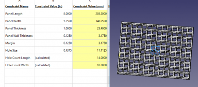
Universal Power Panel Generator - FreeCAD File: File:UniversalPowerPanelGenerator.FCStd
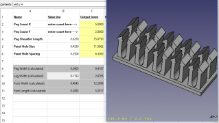
Universal Peg Array Generator -FreeCAD File: File:UniversalPegGenerator.FCStd

Generated Files Assembly - FreeCAD file: File:GeneratedPanelandPegAssy.FCStd


December 29, 2019
Had Audrey start hoeing out the soil to spread it. Need more hoes and rakes.
Sketchup of worksite:Github Link
December 26, 2019
Sent in 11ga CNC parts for quote. File:SoilMixer2019DXF.zip
Made video stepping through series hydraulic circuit. Really high flow when cylinder bottoms out - not sure where that's coming from but I don't think it's realistic. Not sure.
Updated BOM to reflect fittings visible in freecad pic from yesterday. I'm using 3/4" fittings instead of 1/2". This may be a poor decision from the standpoint of cost. I also updated the hydraulic hoses. I think the BOM is ready to go for the hydraulics department.
Soil mixer todo:
- Order Steel
- Order surplus center stuff
- CAD of motor mounts (rotor and doser)
- Add a leg for doser
- Finish controller BOM
December 25, 2019
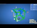
The earlier attempts at a hydraulic circuit had the constraint of a maximum of 10gpm to the hydraulic cylinder valve. If this constraint is lifted, the circuit is simpler to produce. I believe the circuit shown now at Soil Mixer 2019/Controller#Hydraulic Circuit Simulation is capable of doing what we need safely. Please review.
Learned about cylinder regeneration circuits where extension travel speed can be increased by plumbing rod end flow to valve inlet.
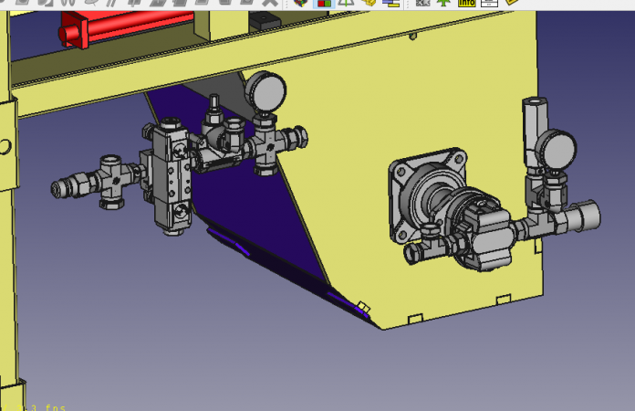
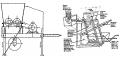
Hydraulic Circuit next to Soil Mixer. Sol Valve shown is Eaton Vickers type used here for convenience.
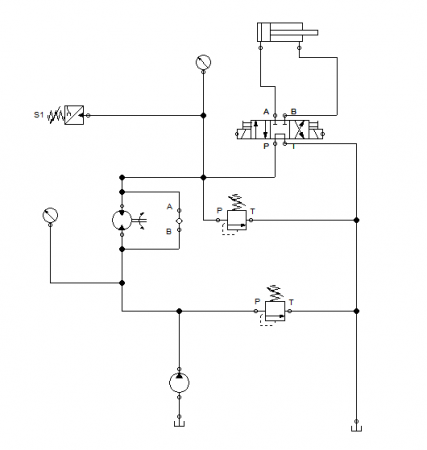
This schematic shows an extra pressure relief valve not needed (included in PowerCube)


December 20, 2019
I thought of a much simpler circuit that might achieve what we need. I was going for the complex circuit because of inspiration from an agricultural implement but what about a much simpler circuit with just a flow control. I made a video to show this circuit. Series with Flow Control (4th video)
File:SoilMixerFluidSIMCircuits.zip - Created in FluidSIM which you can download as a demo and get 30 mins free.
| Sequence Circuit No Relief | Sequence Circuit Draft 1 |
|---|---|

|

|
| Soil Mixer Hydrauilics | Hydraulic Sequence Valve Manifold (should be a female quick connect fitting on the input) |
December 19, 2019
Improved hydraulic simulations are at Soil Mixer 2019/Controller#Hydraulic Circuit Simulation
Sent in the File:SoilMixer2019DXF.zip for quote for cnc plasma.
I think if we do sequence valve we should get a medium setpoint model.
December 18, 2019
I put some circuit simulations on the mixer controller page. If we do a series connection then switching via high pressure is not advisable unless a component is added to let the motor freewheel without flow. What would happen when you bottom out the cylinder is that no flow exists through the cylinder/motor circuit and the pressure spike opens the bypass valve and all the flow goes there. So the motor suddenly has no flow but it is spinning and needs flow to keep spinning. We would need to add a component to let it cycle its own oil or something. Not sure how to do that. If we don't switch the cylinder using high pressure then it isn't an issue. Any small no flow instance would have a braking effect on the motor. I believe they sell a part that lets hydraulic motors freewheel when used with cylinder valves.
In the sample circuit i simulated based on the weed badger the pressure at the pump outlet was always high. I'm not sure what I need to optimize the circuit. I found that by putting the cylinder valve's tank connection to the motor input via check valve it created more flow through the motor than the pump output. Sounds crazy.
December 17, 2019
Soil_Mixer_2019/Controller Hydraulic Valve#Sequence Valve
December 14, 2019
Soil Mixer BOM nears completion.
December 13, 2019
December 8, 2019
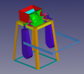
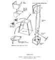
One way to attach the stabilizer doser
Slide auger tube into welded flange tube on mixer body and bolt hopper to grey bolt plate.
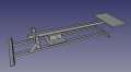
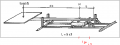
| The mixer has to toss the material 32" on the X axis and about 24" above the mixer drawer in order to directly load into the CEB press. If we raise the mixer up on feet then it doesn't have to throw as high. The drawers could be level if we wanted to raise it up that high. | 
|
December 7, 2019
Adding fingers and slots to chamber parts. Started doing circles in slots as clearance in corners after a while. Recorded a video and put it at Poka-Yoke. Also figured out an improved workflow for dxf creation so that circles are actually circular and not 13-gons. Requires inkscape. Using deepnest to nest parts in a 4x8 sheet looks like we could get everying from 1 sheet if we don't do the arms out of half inch plate. I think 3/8" angle is good and it has lower price per pound.
December 6, 2019
| Item | Amount | Cost ($US) |
|---|---|---|
| Labor | $100/day | $300 |
| Lime | 73 bags | $438 |
| Sand | 1 Load | $100 |
| Clay | 1 Load | $80 |
| Fuel | 1gal/hr. 5.5bpm: 6hrs machine run time | $30 |
| Water | 100 gallons | $20 |
| Total | $968 | |
| Per Block | $0.48 |
| Item | Amount | Cost ($US) |
|---|---|---|
| Labor | $100/day | $300 |
| Lime | 37 bags | $222 |
| Sand | 1 Load | $100 |
| Clay | 1 Load | $80 |
| Fuel | 1gal/hr. 5.5bpm: 6hrs machine run time | $30 |
| Water | 100 gallons | $20 |
| Total | $752 | |
| Per Block | $0.38 |
Water, soil, and clay estimations may be low. We will have more than 1 load of each material on site. I was estimating 1k block per 15 cubic yard dump truck but i don't know if we have a full 30 cubic yards of the sand. We will have up to 10 loads of the clay available.
| Item | Amount | Cost ($US) |
|---|---|---|
| Labor | $100/day | $400 |
| Lime | 110 bags | $660 |
| Sand | 1 Load | $100 |
| Clay | 1 Load | $80 |
| Fuel | 1gal/hr. 5.5bpm: 9hrs machine run time | $45 |
| Water | 150 gallons | $30 |
| Total | $1315 | |
| Per Block | $0.44 |
| Item | Amount | Cost ($US) |
|---|---|---|
| Labor | $100/day | $400 |
| Cement | 64 bags | $576 |
| Sand | 1 Load | $100 |
| Clay | 1 Load | $80 |
| Fuel | 1gal/hr. 5.5bpm: 9hrs machine run time | $45 |
| Water | 150 gallons | $30 |
| Total | $1231 | |
| Per Block | $0.41 |
December 2, 2019
CNC plasma place in Spanish Lookout has a 6x20 table and a 5x10 table for CNC plasma. Looks like we can poka yoke the thing. They charge per inch of cut and pierce. I think it's worth it since the real value is creating a design that can be produced by individuals with less fabrication experience.
November 29, 2019
November 27, 2019
Beginning to draw Soil Mixer 2019 with fabrication in mind. Got the rotor essentially where i want it. Need to decide whether to nix the 1" nuts on the outside faces of the rotor. Began mixing chamber.
Soil Mixer 2019 Master CAD Directory
November 15, 2019
Basket Technique Looks like geogrid from ebay with simple nylon rope embedded in the wall is the way to go. Peru Method is to just use rope
November 13, 2019
Added a bunch of pages to Collaboration Architecture
November 10, 2019
![]() Hint: Derive from the Universal Controller as it has the screen already built in
Hint: Derive from the Universal Controller as it has the screen already built in
Belize CEB 16.09 Controller 19.01 Firmware: File:BelizeCEBFirmware19.11.zip
- Added Manual Buttons
- Added a mid-point button to go to move drawer to press position from any stating location
- Added 3 drawer sensors
- Code no longer relies on delays and while loops - fully interruptible for multitasking
Future development desired:
- Status/process control lights for operator feedback without serial communication PC
- Data collection for blocks pressed per unit time etc.
- Maybe integrate a LCD screen
http://img.youtube.com/vi/lLqCIUlUnOc/default.jpg http://img.youtube.com/vi/Lr4ht4F6jxo/default.jpg
| Sensors vs No Sensors
This video shows the machine starting from the PUSHBLOCK part of the auto code. The left video uses sensors, the right does not. Midpoint stop location was wrong on the non sensor version due to a small error. It does not affect the length of the full press cycle. |
How_to_Embed_a_Google_Doc#How_to_Prevent_Google_Docs_from_AutoLoading_on_your_Page
November 2, 2019
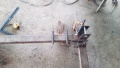
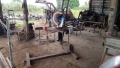
Block breaking apparatus built. Unladen weight is 160lbs.
Block_breaker_4.jpg

Block_breaker_5.jpg
Block_breaker_6.jpg
Block_breaker_7.jpg
Block_breaker_8.jpg
Block_breaker_9.jpg


LB Clay test block tested to 40psi using the formula from new mexico earth construction code.
November 1, 2019
Preparing site for dump trucks in hopes the rain abates. Ram Farm Clay 2 test blocks with 1 part clay to 4 parts sand by weight.
October 30, 2019
Simple unrestrained compression test on a water saturated LB Clay SCEB of 20% sand, 10% cement. 25psi slight failure but not crushed
October 28, 2019
Rammed earth inside pendulum crusher. Rain
October 27, 2019
Put a SCEB out in the rain to see what happens to it. The rain affected only the previously chipped portions of the top face. It's still out in the rain.
October 26, 2019
More Pendulum Crusher

File:Pendulum_Crusher_30.jpg
File:Pendulum_Crusher_31.jpg
- Pendulum Crusher 32.jpg
File:Pendulum_Crusher_32.jpg
- Pendulum Crusher 33.jpg
File:Pendulum_Crusher_33.jpg


October 25, 2019
More Pendulum Crusher
File:Pendulum_Crusher_26.jpg
File:Pendulum_Crusher_27.jpg

File:Pendulum_Crusher_28.jpg

File:Pendulum_Crusher_29.jpg


October 24, 2019
More Pendulum Crusher
File:Pendulum_Crusher_22.jpg
File:Pendulum_Crusher_23.jpg
File:Pendulum_Crusher_24.jpg
File:Pendulum_Crusher_25.jpg


October 23, 2019
More Pendulum Crusher
File:Pendulum_Crusher_18.jpg
- Pendulum Crusher 19.jpg
File:Pendulum_Crusher_19.jpg
- Pendulum Crusher 20.jpg
File:Pendulum_Crusher_20.jpg
- Pendulum Crusher 21.jpg
File:Pendulum_Crusher_21.jpg

October 22, 219
More Pendulum Crusher
File:Pendulum_Crusher_14.jpg

File:Pendulum_Crusher_15.jpg
- Pendulum Crusher 16.jpg
File:Pendulum_Crusher_16.jpg
- Pendulum Crusher 17.jpg
File:Pendulum_Crusher_17.jpg


October 21, 2019
Finalized the sensors on the earth block press. Tested drying the clay under a glass pane during the day. Didn't work due to rain.
Static Crushing Plate and Bearings made for Pendulum Crusher
File:Pendulum_Crusher_10.jpg
File:Pendulum_Crusher_11.jpg

File:Pendulum_Crusher_12.jpg

File:Pendulum_Crusher_13.jpg


October 18,2019
Coded mid-position button.
Began work on Pendulum Crusher at Henrich's welding shop.

File:Pendulum_Crusher_6.jpg

File:Pendulum_Crusher_7.jpg

File:Pendulum_Crusher_8.jpg

File:Pendulum_Crusher_0.jpg


October 17, 2019
Added a mid-point button to the machine so that it will automatically take itself to the obstruct position in manual mode. Cleaned up the wiring of the controller box. Moved the power cube.
October 16. 2019
Went back to Ram's farm for more dirt after results from lab tests came in. "Ram Farm Clay 2" shows promise as a clayey soil to blend with sand. "Ram Farm Sand" has silt and small sand particles but it appears to be coarse and not rounded grains. We dug as much of both as we could. The excavation of the sand was difficult.
October 13,2019
Moved dirt to dry location under a roof due to increasing amount of rain.
October 11 - 12 ,2019
Soil testing Ram's Farm Dirt.
Here is the working document for soil testing: Link
October 10, 2019
Went to Ram's farm to scout dirt. We got three samples. They were all wet as it has been raining a lot here. Two were in piles at the kind of main farm area at the property. They had been dug nearby. One appears to be a montmorillonite clay because of the amount it swelled up when doing a jar test. It is similar to the lagoon sample from near copper bank. There was some large, coarse sand and larger crystal-like rocks distributed throughout it. The second sample was similar in color and showed some plasticity but seems to be similar to marl as it it much less plastic than the clay sample. The third sample is from a ways out in the farm and is sandy with (hopefully) some clay. When damp it can be formed into a ball that does not fall apart without a poke. This may be a sandy-clayey soil suitable for cement stabilization. The samples are being analyzed.
October 9, 2019
Updated the File:CEBPressJuneGroup.fcstd file to reflect the 16.09 machine. Wiki won't let me upload the 4mb file so here's a dropbox link: CEB16.09Belize.FCStd GitHub Link
Changes from File:CEBPressJuneGroup.fcstd:
- Drawer guide system added and old version removed
- 1" drawer guide rods added
- 1/2"x3"x18" flats added to drawer
- Drilled nylon bushings added
- 1" nuts added
- Main Cylinder extended to 16.5"
- Main Cylinder mount plate added to frame
- Shaker system deleted
October 8, 2019
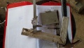
I had the stroke limiter made at the local Mennonite machine shop. They didn't have any solid piece of 5" diameter material so I had to go check the nearby scrap yard. There I found a piece of 4.5"OD, 0.375"wall tube at about 10" length. The guys at the shop machined some 4" round to be a press fit inside the tube which was also machined. It took them about 5 hours to make the part while they also did various other jobs that other customers brought in. The charge was $100BZ, $50USD. I paid $10USD for the piece of tube, less than a dollar USD for the 5/16"x2" grade 5 hex head bolts and $3.00USD for the o-rings.
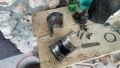
- Making the Stroke Limiter

Preparing to press the disks into the tube
Machining a flat for the hex head bolts and drilling 1/4" hole then drilling halfway with 5/16" drill

Tapping the 1/4" holes 5/16"-18

Parting the tube on the bandsaw.
On Workbench before installing. Notice the shims beside the part

Installed on Machine


October 7, 2019
Tried doing some WebGL stuff yesterday. I can't seem to get any of the loaders to work. No idea what i'm doing in the javascript department but editing the HTML is easy enough. I am pulling examples from the threejs.org website but they don't work with my models. The benefit of doing a loader - be it .OBJ or .glTF - is that your file sizes are smaller. This is important for someone like me on a data connection. For now the FreeCAD WebGL export gives the best looking files though they are larger.
The stroke limiter will have to be 5.5" in height. They have 2.5"ID o-rings at the local hardware store. Hopefully the machine shop can make this. The only tricky part for them will be the counterbore for the socket-head cap screws. I belive they will have a chunk of steel the right size.
I made a drawing for it with TechDraw workbench on. Some features are missing but it's better than the Drawing Dimensioning Workbench that I had been using. Apparently it is being improved upon right now and the next FreeCAD release will have better features. Read about it here: TechDraw FreeCAD Wiki
I don't have a printer so thats why I'm doing the WebGL stuff. It's useful to show the guys in the machine shop since they don't have computers.

The way I would make this:
- In the lathe, drill and bore the 2.5" clearance hole
- Cut the clearance chamfers on either end.
- Cut the o-ring grooves. These are not critical
- In a mill, machine a flat where the the counterbore will go for the 4 holes
- Center drill on that flat and then drill out with a #7 drill.
- Optional: now you can drill out halfway and counterbore the hole so that you can start your tap on the mill if you have that capability. This will make the tapped hole line up perfectly with the clearance hole.
- Part down the middle with a bandsaw
- Tap the tapped half if you haven't already
- Drill out the holes and counterbore the other piece if you haven't already.
- Make some shims depending on the thickness of your bandsaw blade.
October 6, 2019
The reason we can't just use a shim to shim up the press foot 2" is because then we would have to move the press cylinder down due to the overhang at the top end of the stroke. We have to limit the down stroke so that only 8" of material falls into the chamber. .
The drawing below shows a height of 2" this will actually be more because there is some rod exposed (painted black) before the stroke limiter engages the cross welded tube.
October 5, 2019
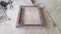
Fabricated a-frame type soil screen. It is immediately very useful.
First trial run of stabilized blocks ended in failure. It took me over a month to realize it but the machine has too much stroke on the main cylinder. It is a 10" stroke cylinder instead of an 8" stroke cylinder that the rest of the machine was designed for. So the blocks emerge between 5.5" and 6" in height and undergo an unconfined compression cycle as they are ejected. This causes them to crack and deform immediately. The drawer then destroys the blocks as it retracts. Terrible.
I need to stroke limit the cylinder. The way we used to do this with pneumatic cylinders was to put a machined disk inside the cylinder to set the stroke to whatever we wanted. I want to limit the retraction so I'm going to use an external stroke limiter that will sit on the rod above the cap end of the cylinder. It should have o-rings or be made of a soft metal as to not damage the rod. Here is a drawing of what it would look like if I were to make it in my machine shop. This would be machined from 5in 6061 round stock. Obviously there are other ways to do it. It could be a square profile. The bottom line is it has to sit on the rod above the cylinder, not damage the rod, be able to be installed without removing the rod, and be strong enough to withstand the forces.
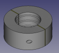
Stroke Limiter
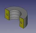
The brass shims make up the kerf lost from bandsaw operation
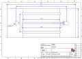
Drawing View. The hole callout says r.137 but it should be a #7 drill. This is tapped 1/4-20 and the other side of the clamshell is drilled out and counterbored for a 1/4" socket head cap screw


The test blocks were made with 20% Sand, 10% Cement, and 70% dirt. The water content was decided qualitatively with the "poke test". I think lower soil:sand ratio is desirable.
September 25 - October 4, 2019
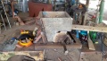
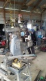
Moving block press site to new location. Setting up site. Fixing my and Scott's trucks. A cane grabber came to unload the block press from the trailer. New site doesn't have electricity yet but it does have running water.
Grinded cassagrande type tool for atterberg liquid limit test.
Layout
- Cassagrande Tool 2.jpg
Finished

September 23, 2019
Playing around with WebGL stuff. Here's a VERY primitive workflow:
- Starting with A2+ assembly file
- Select all on object tree
- Export to WebGL.
- Put resulting .html file in a folder with a subfolder containing three.min.js
- Open resulting .html file in a text editor
- Edit the line where it gets the three.min.js source file as per Michel's instructions.
- Make sure you use three.min.js Revision 50 if you want to go directly from freecad to webgl I upgraded the version on my github.io repo and it caused an issue with trackball controls. I think orbit controls may be superior but the freecad exporter uses trackball
- Also can add antialiasing if desired. See video:
- http://img.youtube.com/vi/18nL5wN8Pbg/default.jpg
- Optional: make an index.html file
- Create a github.io page
- In your github account: Make a new repo with name username.github.io
- My username is CabbageBreath
- Upload your project files to that repo
- https://username.github.io/modelname.html is where the project will be hosted
- My index is at [1]
- In your github account: Make a new repo with name username.github.io
MJ Sez - Nice, results from basic export are quite decent and load pretty fast.
September 22, 2019
My Model of the ITW Clay Crusher
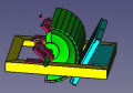
Crusher head detail
My model of the brick crushing apparatus
From the book

Drawing from my CAD model


Modeled the pendulum crusher. I bought a truck wheel rim to cut in half to make this little beast. The CAD is available here: Pendulum Clay Crusher DropBox
The fellow at Parry Building Products uploaded a video of their design which is based on the Intermediate Technology Workshops (ITW) model:
http://img.youtube.com/vi/-XrflpPwegA/default.jpg
I also modeled the Modulus of Rupture (MoR) test jig specified in the Compressed Earth Block Manual of Production. This uses CEBs placed on a platen to apply a force for a three-point-bend test to measure flexural strength of blocks. You can relate this to compressive strength by multiplying by a factor of between 3.5 and 8. The Germans give 5-8 as the factor whereas Krosnowski found it was between 3 and 4.
September 20, 2019
Playing around with sensors on the brick press. The hydraulic system doesn't respond as quickly as I'm used to with pneumatics. This may be due to the landing geometry on the solenoid valve spool being that it is a motor valve. A mid-position sensor is useful for my idea to have a button on the controller case that simply brings the drawer to the mid position no matter where it started from.. I'm using IFM Effector m12 style inductive sensors that I found used in a bundle of 8 for $60 on eBay. Cables I got from automation direct. They're pnp 12v. Works fine with the arduino.
September 19, 2019
Welding repair of Scott's riding mower deck
September 18, 2019
Sieve testing LB soil. CEB_Microhouse_Build_in_Belize/Notes_9-18
September 17, 2019
pH tests for lime stabilization. A 10% stabilization gave 12.1pH. The Little Belize clay may not be suitable for lime stabilization based on this test result.
Did the 10% test twice
| Lime Percentage | Weight of Soil (g) | Weight of Lime (g) | pH |
|---|---|---|---|
| 2.5% | 24.375 | 0.625 | 11.7 |
| 5% | 23.75 | 1.25 | 11.8 |
| 7.5% | 23.125 | 1.875 | 11.9 |
| 10% | 22.5 | 2.5 | 12.0/12.1 |
Used the cement mixer to mix LB soil with sand. It works well for smaller batches. Good for mixing the test blocks.
Started welding up the soil screen which is just an a-frame with expanded metal that you screen the dirt through before mixing.
September 16, 2019
Running around Corozal getting immigration paperwork done for another month. Having my truck here makes it more diffficult.
September 15,2019
Integrated automode into manual button code. I'm taking a similar approach to 2014 to avoid relying on while loops and delays. File:Controller v19.01 Belize.zip
Updated logs. I have poor access to internet here so I just write notes on my smartphone. will try to get better about documentation and uploading multimedia.
September 14,2019
Went to L.B. to talk to Bernhart about setting up the excavation of his site. Aiming for 24th. Looked for dump trailer options. Painted CEB press with Scott, Cecilia, and Evelyn. Finished sieve collection box. In LB went to an auto salvage yard where they have many heavy duty truck parts for sale. I will to to make use of this "graveyard" to source parts in the future. Bought a wheel rim for $15 for the pendulum crusher prototype.
September 13, 2019
Still getting the high pressure issue. Pressure builds, the powercube bogs down, the gauge drops to 0, and the powercube stays loaded and the cylinders don't move. Thinking I got some dirt in the system and the valves are stuck, I take them off the block and look for debris. I also check that they are shuttling when powered. They look great.
Afraid it was due to the pilot operated check valves I installed so I removed them and reinstalled system to original spec. Same issue.
Took the fittings on the manifold input off and I found that the input quick-connect fitting (female) had failed and that pieces of metal were in the system. I found all the broken pieces (i think) and replaced the quick-couplers with a 1/2"npt coupler.
The system works great. Reinstalled pilot operated check valves and the system works greater. The cylinders have good speed and they don't drift.
I could have installed the EATON VICKERS solenoid valves we have here but they draw more current than the relays on the HI LET GO relay shield are rated for. A lower current draw cylinder valve would be more expensive than the pilot check valve system. Also the motor valves still give more flow.
September 12, 2019
Fully integrated the pilot-operated check valves. They are now installed on the manifold. This required me to flip the ports so that the retracts are on the A ports and the extends are on the b ports. Just a piping issue. I simply switched the wires in the solenoids.
Worked great until suddenly it didn't. I would get high pressure and then not be able to change direction. I thought the solenoids were getting stuck as if I accidently let some dirt in to the system when I was doing the modifications or there was an electrical problem. I opened the covers and saw there was water damage in the electrical connection. Upon taking it apart the screwheads stripped since the insert nuts they interface with were rusted. The heads were super soft and stripped very easily. Only one solenoid connector was damaged. Lots of solder later it works great. Lost a flyback diode in the process. Running without one right now.
September 11, 2019
Trip to Orange Walk. Acquired 8kw gas generator. Caulked the lowermost sieves.
September 10, 2019
Installed pilot operated check valve on the press cylinder. This was installed temporarily on the hoses that lead to the press cylinder. Works great. 1/4" signal hose had a pinhole leak out of the box from surplus center. Don't seem to reduce flow too much.
Pressed a test block with the little belize clay. Cut it with some sand. Still setting up block testing so nothing scientific yet.
September 9, 2019
Manual control buttons fully integrated. Automode switch installed.
September 8, 2019
For the buttons I initially wanted to switch 12v since the 5v regulator had already failed once. I'm now using an LM7805 regulator with +12v Positive and Negative leads to the bus bar and the 5v output put into the +5v rail on the double row header. Looking back it was a bit more than necessary but I wanted to switch the 12v with the switches and step it down with a voltage divider directly to the output pin for the relay. The issue is that when a pin is configured as an output it's input impedance changes and messes up the voltage divider. I didn't want to go through the microcontroller for the buttons but I couldn't find the right amp-rated momentary switches in time so I had to order the ones I got. They're IP67 rated momentary switches that are NO. They switch GND to inputs configured with internal pullups.
I had an issue with a placement of a parenthesis in my program that cost me a good hour (i'm not proud to say). Changed up the controller box by switching the outlet box used as a spacer with a piece of wood so that I could fit more arduino shields on the arduino.
I bought a shield for doing IO prototyping. This is the one I got: link. I don't recommend it. It's fine but I would get a simple protoboard without all the bells and whistles. Something like this I also got these screw terminals link and some 10k and 18k resistors for 12v to 5v signal conditioning.
September 7, 2019
Went kayaking.
Started adding controller buttons for manual control.
September 6, 2019
Shopping. Went to Ram's place to get parts from USA. Electronics and hydraulics.
September 5, 2019
Picked up Scott
September 4, 2019
Finished sieve boxes. Adapted vibrating pedestal thingy to work for vibrating the sieve boxes.
September 3, 2019
Went to Bernhart's house. Bernhart is a Mennonite fellow that works at the LB hardware. He invited us over because he wants to dig a pond and will give his clayey subsoil to us. He wants us to pay for the excavator at $125/hr. It's 18mi to Copper Bank from the dig site.
September 2, 2019
Finished painting cement mixer. Worked on sieves.
September 1, 2019
Made more cuts for the soil sieves. I feel strongly they should be made with notches so I'm waiting to have Noae cut the notches on his tablesaw. Once the sieves are done the work on the soil testing can begin.
Prepped and painted cement mixer with Harrol. Ran out of paint 3/4 the way through.
I crushed the lagoon clay and ran a jar test with it. I had to stir the mixture to get it to mix properly. Shaking did not suffice. The next day the specimen had swelled up to twice the marked level. Extremely expansive. I need to test this more thoroughly.
August 31, 2019
Day off. Did some A2+ style modeling of Soil Mixer 2019. Need to do hammers and then start on mixing chamber.
August 28, 2019
Trip to Corozal. Got paint for cement mixer. Tablesaw motor brush wore out. Glue repair held strong. New brush on order.
Went to Noe's house to rip the sapodilla wood for the sieves. He did a fine job and only asked to be compensated a dollar. He built his own tablesaw.
August 27. 2019
Got the machine to run pretty well with some code adjustments. I now drop the main cylinder for a half second before moving the drawer to the eject position. The machine would give high pressure if I didn't do that and the ejection would fail. Haven't tested it with soil in yet.
Repaired a melted tablesaw motor with some JB weld so that I can make the soil sieve stack.
Went looking for more clayey soil. It's mostly marl in the immediate vicinity. I ended up bringing home a wheelbarrow full of some clayey topsoil. Not ideal but better than nothing. I need to go to Little Belize and figure out where their clayey road soil comes from.
The marl test block we made seems to be getting stronger as it cures. It deserves some closer attention.
August 26, 2019
Worked on aligning the brick press and tightening any fasteners that may have been loose. I played around with putting shims in to get the drawer to be square with the machine before realizing that it really doesn't matter since the squareness of the bricks depends on the inside of the press chamber and not the drawer. The drawer just provides the top surface. THe only thing that matters with the drawer is that it doesn't deflect when pushed up against so that the top and bottom faces of the block are parallel.
Later in the day we pressed some blocks using the marl beneath our feet. Screened with 1/4" screen and varying amounts of moisture added. No objective measurements. Just a little ball test to get in the right range. We pressed the blocks manually since the auto code still isn't optimized. This is a tedious process that requires turning on and off the power cube and disconnecting hydraulic hoses and using a jumper wire to turn on and off the solenoids. First extend the drawer and drop the main cylinder. When the main cylinder is at its limit turn off the power cube and disconnect the main cylinder hoses. Then turn on the power cube and move the drawer to the obstruct position. Then turn off the powercube, reconnect the main cylinder hoses, turn on the powercube, press the block, drop the main cylinder all the way and move the drawer to its home position. Wait for the block to rise and then push it out. Very tedious process and jumping the wires makes it even more so. We pressed three blocks. THe first one had enough clean surfaces to see how square the block was. It appeared to be square to a 16th of an inch on most sides. The marl doesn't have enough binder in it to work as a good CEB material. It shattered with a light punch. We added more moisture to the next blocks but they were too wet and water seeped around the block as it was ejected. Still it held its shape and we left it to dry.
At some point the 5v regulator stopped putting out 5v and the arduino won't drive the relays anymore. I have to have a usb connection to make it work.
August 24, 2019
Reversed logic of pressure switch in code to match reality. It's a NO pressure switch and we are using pullup resistors so we are feeding 5v on pin 13 to one side of the switch. The other side of the switch is GND so when we connect pin 13 to GND we should get a LOW on pin 13. The program was looking for a HIGH instead of a LOW.
We adjusted the pressure switch with an ohmmeter and a jumper cable. Since there is no provision for manual control we had to jumper 12v to a solenoid with a wire to trigger a high pressure for setting the pressure switch. Connect the ohmmeter to both sides of the switch with the leads disconnected and trigger high pressure. While creating high pressure in the system in short bursts, tighten the screw until it no longer reads connectivity and then back the screw off until it just reads connectivity at high pressure. It's a 3mm hex wrench in the pressure switch on the machine.
Added serial communications to the code for debugging. Each state of the cycle will generate text indicating where it is. As does high pressure.
First real issue was that if you wait a long time to switch to press mode from reset mode after the reset homing is complete then it will think that it took a long time to extend the drawer. It then scales this long time (15s or more maybe) to retract to mid-point but even 5 seconds of retraction will take you to the end of the stroke so you will bottom out and the code doesn't look for high pressure. It's just delaying. This is the issue with delays. Eventually I will rewrite the code to do away with delays and while loops but for now I just band-aided that step by replacing the delay with an if and while statement.
This is the original:
                                                 //Step 2 Compression Chamber Closure
if (resetSelected() == false) {
 digitalWrite(SOLENOID_RIGHT, HIGH);
 delay(drawerExtTime*0.75*0.5);           //0.5 is the half-way point of drawer cylinder; 0.75 is the Drawer Multiplier
 digitalWrite(SOLENOID_RIGHT, LOW);       //Can modify the 0.5 to fine tune the drawer closure location
}
This is the version that will move to mid point or until high pressure is read:
//**********************************Step 2 Compression Chamber Obstruction*********************************************
if (resetSelected() == false) {
 Serial.println("Moving Drawer to mid position");
 if(digitalRead(SOLENOID_RIGHT == LOW) ) {
   Serial.println("Current Time:");
   Serial.println(millis(), DEC);
   obstructMoveTime = drawerExtTime*.75*.5 ;     //Duration that the solenoid will be on
   Serial.println("Obstruct Move TIme:");
   Serial.println(obstructMoveTime,DEC);
   drawerEndTime = millis() + obstructMoveTime ; // calculate the time the output should turn off
   Serial.println("drawerEndTime Calculated");
   Serial.println(drawerEndTime,DEC);
 }
}
 Serial.println("here1");
 while (millis() <= drawerEndTime){
    if(checkPressure() == true){
       drawerEndTime = 0;
     }
     digitalWrite(SOLENOID_RIGHT, HIGH);
     Serial.println("here2");
     Serial.println(checkPressure(),DEC);
 }

//delay(drawerExtTime*0.75*0.5);           //0.5 is the half-way point of drawer cylinder; 0.75 is the Drawer Multiplier
digitalWrite(SOLENOID_RIGHT, LOW);       //Can modify the 0.5 to fine tune the drawer closure location
Serial.println("Drawer at mid position");
delay(3000);                             //Delay for slowing operation down for debugging
It's not beautiful but it works for now. In order to do the digitalRead on the solenoid output I had to change the #DEFINE SOLENOID_RIGHT to an int SOLENOID_RIGHT = 0; so that its state can be read.
I also dropped the 20ms pressure switch debounce to 5ms. This appears to help timing overall. I can reduce it even further. 5 was arbitrary. I think 2ms would do just fine. Gotta research that but i don't think contacts bounce for more than a ms.
The drawer extension time measurement is consistently too short. Common values are around 1.7s. This means that the chamber doesn't obstruct fully. This is due in part to the fact that the drawer cylinder isn't starting at its actual home position. High pressure on the main cylinder (second in the series manifold) causes the drawer cylinder to bump forwards a bit more than an inch by the time it goes to extend from fully retracted to fully extended. So I know that this is causing short extension times. There may also be a problem with the way the code is measuring. Changing that debounce value shifted the times longer so that definitely helped.
I need to get the hydraulics in order (press cylinder moving forward due to main cylinder pressure events) but first we need to square the machine up mechanically. It's not square whatsoever. Next step is to loosen all the fasteners, align everything, and retorque the fasteners.
The powercube is running well. The CEB press seems like it will shake itself apart every cycle (as always) and Cecilia went running the first time I ran a cycle. Some hydraulic fittings are leaking. A vise is on my wishlist. Adjustable wrenches will have to do for now. Hopefully i'll get internet access soon to upload multimedia.
The clayey dirt from the mennonite roads expanded a bit more than the marl in a jar test. Still it's more clayey so cutting it with sand might yield good material. Soil testing has been on the backburner because I'm trying to get the press to make a block before Scott leaves on Monday.
August 22 - 23, 2019
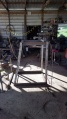
Worked on repairing Scott's old broken cement mixer. Frame is bent and keyway in shaft is worn. Rody, Harrol, and I are reinforcing the frame.
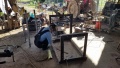
Built a workbench to work at near the machine. Started looking at the controller and code. Found a potential issue on line 102. The instruction is to turn off the drawer cylinder instead of the press cylinder. I also noticed (and this is just a stylistic thing) that often there are if else statements when a simple if statement will suffice - there are no arguments in the else portion. I'm going to have to update the code when I add the manual buttons so i'll upload my version when the time is right.
I think there is a need for manual mode because if someone gets their finger or arm stuck in the machine there is no way to move the drawer to help them.
Scouted soil at Scott's first 60acre jungle property. Clayey soil under a decent topsoil layer. Didn't take samples but will do so at a later date.
August 21, 2019
Went to "Little Belize" which is a Mennonite community where they have a lumber yard and a hardware store. The hardware store sells some metal. I bought 40' of 1/8" x 1 1/2" angle, some flattened expanded metal, and some 4x4 screen to make a screen for sieving soil for production. I also picked up some 3/4" x 4" x 84" hardwood from the lumber yard for making the sieves. I brought down 12"x12" soil screens from mcmaster to reduce the price of a soil sieve set. The lumberyard has SO MUCH HARDWOOD!!!! SO CHEAP!!! It's incredible. and they let you pick through the reject lumber for free.I got what I need to make the sieves and a workbench for $30 US. And this is hardwood, not some shitty pine. I'll upload some videos of their sawmill. They planed the wood for the sieves for me. I will start making them soon.
Spent the rest of the day testing power tools. Tablesaw motor is melted at the brush housings. I'll attempt to fix with epoxy. We have several working circular saws. Gabi Harrol and Scott set up some tarps for sun protection while working.
Adjusting to the heat and sun. It's not much different from Missouri in July but my access to water is different and I'm on other peoples' food schedules and I have an issue with a swollen tonsil that is exacerbated by the amount of talking I have to do. Can't complain though since we're in paradise.
While in Little Belize I grabbed a sample of the clayey soil that they use on their roads. It looks more promising than the Marl. Haven't jar tested it yet. I'll need to get a larger sample after I get the sieves going.
August 20, 2019
First week in Belize. Internet access for now is a hotspot on my phone. Not enough data to upload multimedia yet. There is wifi available somewhere in the village but I haven't been introduced to that person yet. We arrived in the afternoon on Saturday. Spent Sunday and Monday getting settled and taking care of the basic necessities of life. Brought all of Scott's tools to the worksite at Harrol's house.
We successfully unloaded and setup the brickpress and power cube. Arranged them in what I think will be a good workflow. The powercube needed adjustment on the choke cable. The people down here who had tested it had been putting gas down the air intake to start it. I adjusted the cable properly so that the choke comes on when it should and the engine starts without any other intervention. Oil was clean and level looked great. I believe Ram changed it. Hydraulic fluid tank was 3/4 full. Air filter was pristine. Won't need the spare parts for a long time.
We hooked up the hydraulics and powered on the brick press with the controller. It didn't seem to be doing what it should be doing. I need to check the setting of the pressure switch to make sure it's not triggering early. The machine seemed to do the RESET procedure properly and repeat every so often. But when I switched to full brick mode it didn't act right. It extended the drawer all the way and then jerked its way back in maybe 1 or 2 second increments. I didn't have my computer handy to check what the machine thought it was doing. I would have to put some serial communications in the code anyway. I don't have a good workspace set up yet so that's the priority right now.
One thing Scott wants to do is make the machine work in a manual mode. There is no way to do that right now besides using a jumper wire to give power to the solenoids inside the controller box. I don't see any manual override on the valves. The 2014 solenoids did have a manual override but I don't see it here. I ordered some momentary switches that should arrive next week. Later on I remembered that I should have gotten NC switches (best practice) but the NO ones I got should work.
I see that there are spare cylinder (tandem spool) valves down here. They're the Eaton VICKERS brand that Surplus Center sells. I have the hirschmann connectors on order. The issue with these is that they are 3.5 AMP coils. It says 30W on the housing but the catalog says 3.5A. I'll test what it really draws. The relays on the controller are rated for 3A. The relays might work at that current since they're not on for very long. We'll see.
Did a jar test on the marl that they build roads with. Marl is a limestone rich soil. It was pretty expansive. Came out to about 5/16" above my scribed line. Just a preliminary test. It may be useable.
August 6, 2019
I'm very interested in the pendulum crusher from the previous log entry. After a correspondence with the owner of Parry Building product, I'm convinced this is a rugged design and the output is claimed to be 20kg/min. If we assume 1800kg/m^3 1 then it would take 90mins to do a cubic meter or 70 mins per cubic yard. This gives 1.75 blocks per minute, roughly. Slow.
August 2, 2019
Clay crushers
- Pendulum Crusher
ITW WORKSHOPS PENDULUM CRUSHER
See right side of image
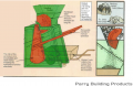
Now manufactured by Parry Building Products.


- Crankshaft crusher:
July 31, 2019
I ordered all the spare parts I think I may need in Belize. The orders are on page 2 of the Tools & Infrastructure spreadsheet at Mader's Machine. I didn't buy a spare pressure relief valve nor any spare hoses. Hopefully the relief valve doesn't kick on, doesn't get hot, and doesn't fail. I did find an alternate pressure switch, New Old Stock from eBay. Same logic and same port size.
Been thinking about the cylinder drift issue recorded at CEB_Controller_v19.01. I read that one way to correct the issue would be to use pilot-operated check valves on the press cylinder. These are $60 from surplus center and prevent a cylinder from moving unless powered.
I do see what Marcin is talking about with the "motor spools" being higher flow than the "cylinder spools". Yuken and Northman both give lower flow rates for tandem(C6) spools vs open center(C3) spools. For Yuken it's about half; for Northman it's about a third less.
I know now that motor spools are also called open center spools which is a use of open center that is distinct from the standard open center vs closed center usage. Yes, they're open center but so are tandem valves which connect P to T in center position but block (to the extent that metal seals on metal) flow from the cylinder to tank. Tandem valves should be used in combination with pilot-operated check valves in situations like loader arms so that cylinders only move when the valve is actuated. The pilot op valves would be a safety redundancy.
So I propose we add pilot-op check valves on the CEB press for a total of $155. This is less than an upgrade to higher-flow D05 valves and subplate in a tandem configuration. My quoted cost includes the additional hoses needed. I believe the check valves could be screwed right in to the subplate outputs. We would need to add Tees to port the pilot pressure to the valves.
July 18, 2019
Sketched up a rough outline of an auger-assisted soil crusher. Trying to solve the problem of relying on gravity to meter the dosage of soil and stabilizer. I think a force like that from an auger would help normalize the dosing. I'm not crazy about it but it could work. Maybe too expensive.
July 17, 2019
Don't have edit access on Soil Mixer Design Doc so I'll record my thoughts here:
- What propels the stabilized soil mixture out of the hammermill?
- Relying on gravity and ratio of areas to dose quantities of soil and earth. This, in my opinion, will be irregular. You would have to be able to change the size of the stabilizer aperture in the field.
- Based on pH for lime. Do a sample every so often
- Based on color for cement?
- The raw soil would need to be crushed and dried before it will fall into the drawer in a repeatable way. This kind of defeats the purpose of a hammermill.
- I could see this propagating the error we have in block size throughout the system. Relying on the soil to fall into a hole the same way each time. Might double the error, right? Double the random uncertainty in block size. Or give a systematic shifts in error during a shift or certain working condition.
- An auger system could meter the input of soil and stabilizer in a more controlled way while still using only one actuator (motor instead of cylinder - though maybe it works out to an extra motor). A variable pulley could be used to set the stabilizer ratio. This is an off-shelf item.
- Example of variable speed pulley system. If we use the same auger size for soil and stabilizer, then gear reduce the stabillizer auger to give 3% to 10% the speed of the soil auger. If you need more than 10% stabilizer then you are using a very low clay content soil and using a ton of cement - rethink the soil blend and if you need to, buy a different pulley.
- Does variable pulley work at low speeds?
- Planetary Geardown? 6 axis CNC Torch Table to produce most components of planetary geardown?
July 16, 2019
Tried to go to the dev meeting to discuss soil mixer per discussion with Marcin last week but nobody was there save an AFK Abe.
Need feedback on workshop tools and infrastructure list at Belize CEB. I'm not including any hardware or materials for the house - just the tools that are required to build it. Just working from what I can imagine would be necessary. Another more experienced set of eyes would be good to glance over what I have listed so far.
Thinking about soil prep: for Marcin's hammermill concept, how do we get dirt at OMC (optimum moisture content) before it goes into the hammermill? One way could be to figure out OMC by volume of dry dirt, volume of water and have laborers fill 5 gallon buckets with dry, screened dirt and add water from another bucket with demarcated OMC line. This unmixed bucket of water and dirt goes in to hammermill. Assume that the dirt has (non-uniformly) absorbed the water AND that the hammermill will actually give a homogeneous mix. I don't see why the hammermill would give a homogenous mix unless you cap the mixing chamber to prevent material escaping before a homogeneous mix is obtained. This would take longer than a press cycle so it would have to mix more than 1 block's worth per round.
July 11, 2019
July 5, 2019
CADded D3D Mill assembly in 2 days
June 20, 2019
June 16, 2019
File:Taper to Straight adapter.fcstd File:Taper to Straight Adapter Wheel Hub.fcstd
Feb 25, 2019
I made a new tube builder when I heard mine wasn't working in FreeCad 0.16 on Ubuntu.
The new file is based on the Sketcher, Draft, and Part workbenches whereas the original file was based on the Sketcher and Part Design workbenches.
File:Alternative Universal Tube Builder.fcstd
Here is a video explaining the new file approach
Feb 23, 2019
Video showing making of a spreadsheet parametrized cad file.
Feb 22, 2019
Made a video about the tube generator and improved the file by adding HoleSpacing parameter to spreadsheet.
Nov 20, 2018
Here is a version uploaded to the OSE Wiki. It should work but may have design flaws. I'm using an O-ring to seal the cylinder in the cap trepan groove. This is questionable.
File:Universal Cylinder Builder ADW.FCStd
I've been working on a cad file for the Open Source Cylinder. Here is a link to the alpha stage of the file. DROPBOX The end-caps are square with a trepan machined for the tube to seat. The caps could potentially be parted so that a welding operation replaces a machining operation for the tube seat. The Rod is welded to the Piston in my version.
Like the universal tube builder, I'm trying to make it parameterized from a spreadsheet. Here is what the parameters look like right now:
Name	Input (Inches)	Output (mm)	Note
Cap Side Length	4	50.8
Cap Thickness	1	25.4
Tube OD	3	38.1
Tube Wall Thickness	0.25	6.35
Piston Thickness	1	25.4
Piston Seal Inner, Height	0.3125	7.9375
Piston Seal Inner, ID	2.125	26.9875
Piston Seal Inner, OD	2.5	31.75
Piston Seal Outer, Height	0.25	6.35
Piston Seal Outer, ID	2.125	26.9875
Piston Seal Outer, OD	2.5	31.75
Stroke	12	304.8
Rod OD	1.5	19.05
Rod Stickout	2.5	63.5
Cap Seal Outer, Height	0.25	6.35
Cap Seal Outer, OD	2	25.4
Cap Seal Outer, ID	1.495	18.9865
Cap Seal Inner, Height	0.25	6.35
Cap Seal Inner, OD	2	25.4
Cap Seal Inner, ID	1.495	18.9865
Need to add a few parameters like tie-rod diameter. I think the model may need to be scrapped. Especially if one looks at the dependency graph lol. I didn't take as intentional an approach to modeling it as I could have.
I believe it is a worthwhile effort, though. A user could generate the CAD for a cylinder of different sizes by simply entering data into a spreadsheet.


Notes
The caps as I have drawn can be easily made on a lathe and mill. How i would make this: Cut the plate to size and machine square. Surface grind for extra credit. Put the four tie rod holes in but make them half inch reams. Using shoulder bolts, attach the plate to a lathe jig or 2 bolts and 2 dowel pins. To make the lathe jig, press fit a piece of 4" or similar crs into a thick plate with the bolt pattern on it and weld. Face the jig on the lathe after welding. The bolt pattern should be put in after the welding operation. Use custom vise jaws and maybe a small bore for picking up the center. For the rod end cap, drill and bore the rod hole then bore internal grooves. Then cut trepan groove. For the base, it's just a trepan. Make those in half a day including making the jig.
As an alternative, I was imagining "slicing" the caps into layers, like 3d printing, and then welding the slices together.
For plastic cylinders, I would start with pvc or abs pipe as the tube. I'd go down that road before I started messing with a metal prototype.
I'll keep thinking about it.
Aidan
Nov 5, 2018
Here is a file that might be helpful for y'all. Open the Universal Tube Builder file and use the spreadsheet to create tubing with all dimensions parametrized. Holes will automatically be set to 4" spacing. I can change that if you want. You can define the standoff for the first hole.