D3D Australia: Difference between revisions
mNo edit summary |
No edit summary |
||
| Line 28: | Line 28: | ||
===Notes=== | ===Notes=== | ||
[[File:Outside_inside_corner.jpg]] | <iframe[[File:Outside_inside_corner.jpg]]frameborder="0" width="960" height="569" allowfullscreen="true" mozallowfullscreen="true" webkitallowfullscreen="true"></iframe> | ||
Revision as of 06:45, 20 December 2017
Basics
- This is a replication of the D3D 3D Printer
- It was made in Emerald, in the Central Highlands region of Queensland. Australia.
- It was made by (Insert Name(s) Here) on D/M/Y
- It used the metal frame option.
BOM D3D Australia
Log:
Wed Dec 20, 2017
Assembly
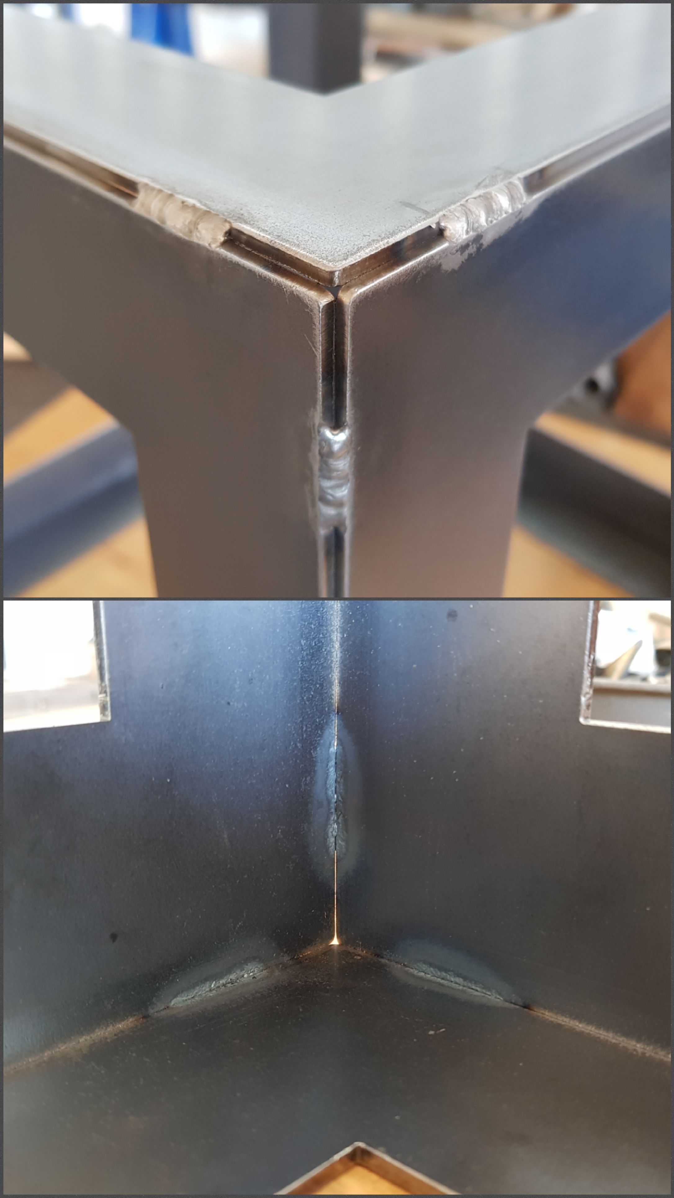
Finished stitch welding the frame and painted it.
Notes
<iframe frameborder="0" width="960" height="569" allowfullscreen="true" mozallowfullscreen="true" webkitallowfullscreen="true"></iframe>
Tue Dec 19, 2017
Assembly
Removed brim from new set of Carriage Side and assembled them. The carriages slide with no resistance on the shafts. Started cleaning the frame for painting and the epoxy glue started cracking in parts and separating from the frame in others. I am not sure about the reasons but it could be a combination of factors. I disassembled the cube and started from scratch. This time I decided to weld it with a TIG machine. I only tack welded it at this point.
Notes
The idea of the metal frame is appealing because of its structural rigidity, and one also needs to consider that it was designed with the use of magnets for the axes in mind. Nevertheless, I found the assembly of the frame to be a rather cumbersome process without a precise way of squaring the corners. I would consider alternatives in a future build. Used a ZAP brand clear epoxy glue for the frame's first assembly, for the record.
The 3D printed parts with the brim are pretty much perfect.

Mon Dec 18, 2017
Assembly
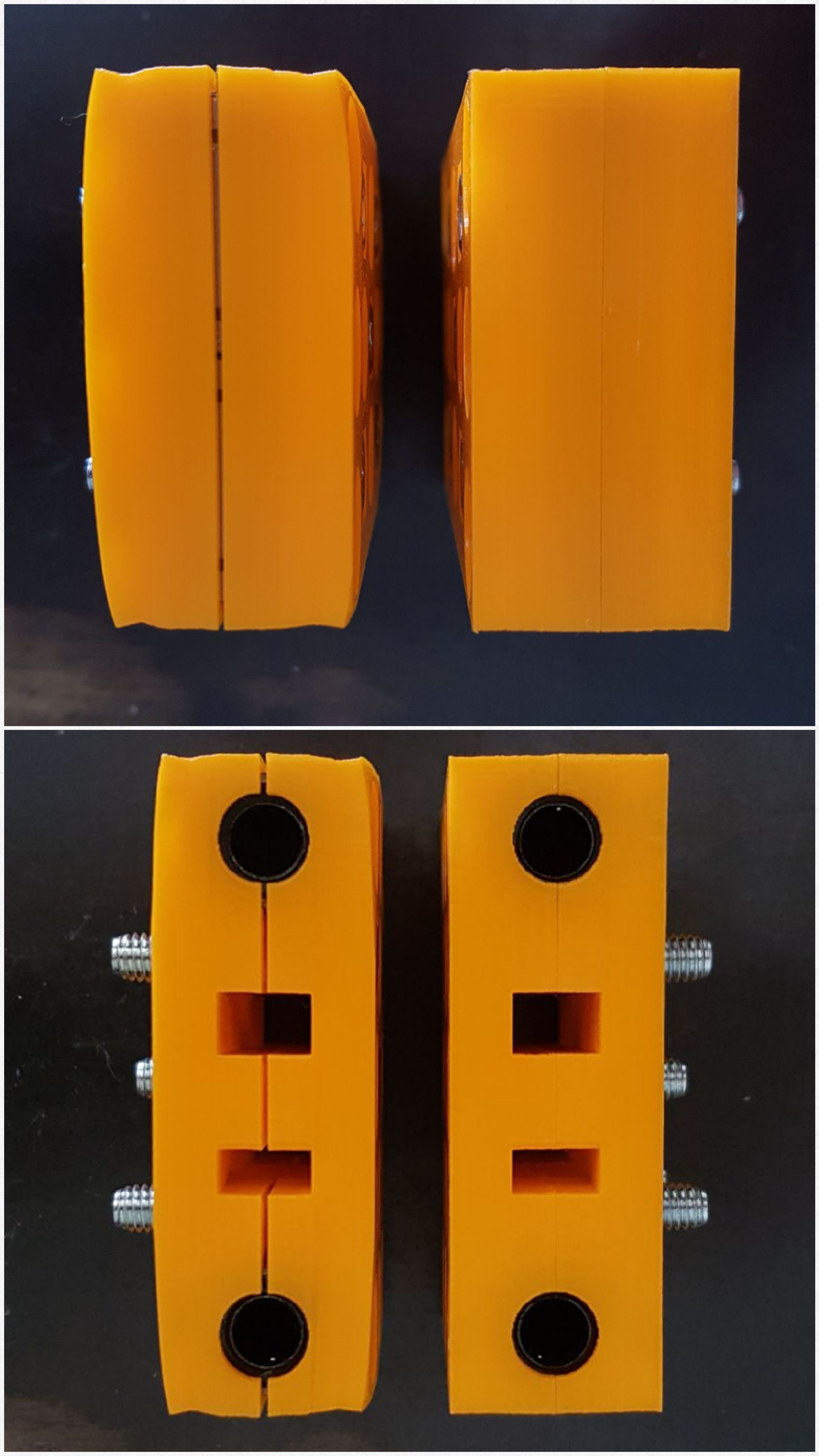
Assembled two carriages and checked alignment of linear bearings on one of the assembled axes' rods. Bearings are slightly misaligned due to warping of printed parts.
Printing
Carriage Side parts are fairly warped, in part due to printer settings.
Created a new .gcode file for the Carriage Side to try to reduce the warping on these parts.
Printer settings for PLA plastic:
Layer height: 0.2mm
Shell thickness: 1.2mm
Bottom/Top thickness: 1.2mm
Fill density: 25%
Printing Speed: 50mm/s
Printing temp: 200 C
Bed temp: 50 C
Nozzle size: 0.4mm
These settings are, at this time, random aproximations based on basic configuration across different machine models for PLA.
Notes
Brought the printing settings back to default, reduced the HBP temperature to 50 deg C and added a brim in an effort to minimize warping.
Sun Dec 17, 2017
- Started this log.
Printing
Generated .gcode file for Carriage Side and started the printing process. Estimated printing time for one set of four parts is 11:00:00. Eight of these parts are needed (two sets with current .stl file layout).
Printer settings for PLA plastic:
Layer height: 0.2mm
Shell thickness: 1.6mm
Bottom/Top thickness: 1.5mm
Fill density: 25%
Printing Speed: 50mm/s
Printing temp: 200 C
Bed temp: 70 C
Nozzle size: 0.4mm
These settings are, at this time, random aproximations based on basic configuration across different machine models for PLA.
Notes
Sat Dec 16, 2017
Assembly
- Glued the last 16in square to the frame and trimmed excess epoxy (+-1 hour).
Printing
- Printed a second set of Motor Side assembly. Eight of these parts are now ready. Two for X-axis, four for Y-axis and two for Z-axis.
Printer settings for PLA plastic:
Same as previous day.
Fri Dec 15, 2017
Assembly
- Preparing (straightening bows, sanding of edges, degreasing), squaring and gluing of 16" D3D frame (+-4 hours). As with the first set of squares that I got cut out, all of these squares presented some degree ob bowing due, I believe, to the heat generated by the cutting process on a plate that, at 3mm, is relatively thin.
- Put together some of the axes' parts to check the squareness of the 8mm rods. Prints are very precise. Rods are parallel across all planes. Assembled HBP support. Possible issues could be sagging of the far end of the heated bed after some use and jittering of bed if Z-axis needs to work too hard for the auto leveling during the printing.
Printing
- Short Iddler Side printed successfully. Elapsed time: 09:43:00. Created .gcode file and started printing another set of parts: Motor Side Estimated printing time for one set of four parts is 10:20:00. Eight of these parts are needed (two sets with current .stl file layout).
Printer settings for PLA plastic:
Layer height: 0.2mm
Shell thickness: 1.2mm
Bottom/Top thickness: 1.2mm
Fill density: 30%
Printing Speed: 50mm/s
Printing temp: 200 C
Bed temp: 60 C
Nozzle size: 0.4mm
These settings are, at this time, random approximations based on basic configuration across different machine models for PLA.
Thu Dec 14, 2017
Printing
- First set of parts printed with a fault (shift on Y-axis position halfway through the printing process). Replaced end-stop micro switch. Checked motor driver. Swapped X-axis driver with Y-axis driver. The problem seems to be solved. Probably just a bad contact in the driver's connection. Created .gcode file for Extruder Holder. Extruder holder printed successfully. Created .gcode file for Short Idler Side. And started the printing process.
Printer settings for PLA plastic:
Same as previous day.
Notes
Bridging. There are strings of filament that did not anchor to the edges of the magnet's socket-bases and nut's socket-bases. The filament fell into these socket's space during the printing process. Part of the problem is due to gaps in the printed perimeter of the sockets. These gaps are the result of the proximity or intersection between the perimeters of various sockets with each other and with the outer shell of the part.
Suggestions
Check .stl and .fcstd files to try to solve this issue.
Wed Dec 13, 2017
I have all the parts required except for the 3D printed parts. I am printing my own parts and I will be learning the basics of the printing process as I move along. For this reason, this log will contain some details concerning printer settings that I will be trying with the different parts necessary for OSE's design. These settings may or may not be of use later on but are, I believe, a good reference point.
Printing
- Started printing first set of parts Motor Side.
Printer settings for PLA plastic:
Layer height: 0.2mm
Shell thickness: 1.2mm
Bottom/Top thickness: 1.2mm
Fill density: 25%
Printing Speed: 50mm/s
Printing temp: 200 C
Bed temp: 60 C
Nozzle size: 0.4mm
These settings are, at this time, random approximations based on basic configuration across different machine models for PLA.
See Also
- D3D
Usefull Links
-