LifeTrac: Difference between revisions
Andrew Buck (talk | contribs) m (adding cat) |
m (→Wheel Motor Control: Updated broken URLs to Surpluscenter) |
||
| Line 174: | Line 174: | ||
A 50/50 flow divider is recommended to make sure that if the front wheels come off the ground with the loader, the back wheels still have adequate flow. Without using a divider, the wheels that come off the ground will spin fast and back wheels will stop - because hydraulic fluid takes the path of least resistance. | A 50/50 flow divider is recommended to make sure that if the front wheels come off the ground with the loader, the back wheels still have adequate flow. Without using a divider, the wheels that come off the ground will spin fast and back wheels will stop - because hydraulic fluid takes the path of least resistance. | ||
One way to address this is with a 50/50 rotary flow divider. Expensive option - such as this 21 gpm divider from Surpluscenter - [[ | One way to address this is with a 50/50 rotary flow divider. Expensive option - such as this 21 gpm divider from Surpluscenter - [[https://www.surpluscenter.com/item.asp?UID=2008101313500912&item=9-5120-21&catname=hydraulic]] | ||
What are alternative routes? What about a simple ''adjustable flow control valve''? | What are alternative routes? What about a simple ''adjustable flow control valve''? | ||
Would a 50/50 flow divider work - [[ | Would a 50/50 flow divider work - [[https://www.surpluscenter.com/item.asp?UID=2008101313500912&catname=hydraulic&qty=1&item=9-1048-c]] | ||
==Schematic== | ==Schematic== | ||
Revision as of 05:52, 9 June 2011
Main > Food and Agriculture > Farm equipment > LifeTrac
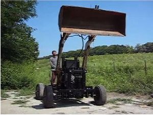
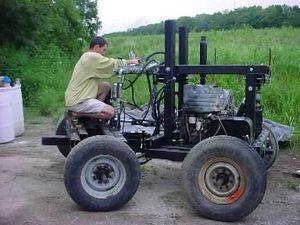
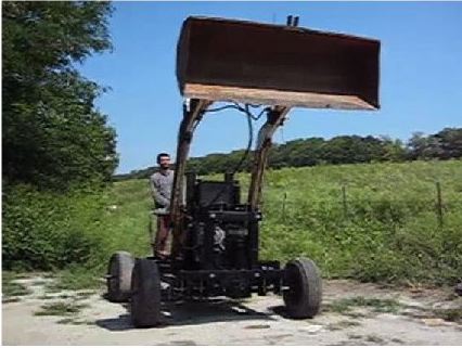
LifeTrac is a low-cost, multipurpose open source tractor.
Prototype I
Prototype II
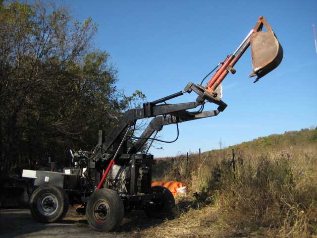
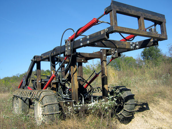
Prototype III
Coming May, 2011.
One possible concept:
LifeTrac Concept
LifeTrac is an open source tractor/ loader. It is an articulated tractor that steers by bending in the middle. It also has a flexible coupling between the front and back, so that the wheels stay on the ground at all times.
The concept was inspired initially by CADTrac, a set of plans that you can buy:
But it is redesigned thoroughly by enlarging the size and making construction simpler, to fulfill OSE Specifications for Post-Scarcity Economics.
Goals
- Lifetime design
- Scalable
- Modular
- Easy to maintain
Features
It has a number of features that set it apart from skid loaders and make these vehicles suitable for agriculture. The main features for agriculture are a 3-point hitch, power takeoff, and high-flow hydraulic takeoff. These features make the LifeTrac capable of using any agricultural implements.
LifeTrac is also designed with a winch, and is designed to be equipped with well-drilling equipment with 10-foot drilling pipe sections.
As such, the design is one of highest utility and versatility, combining the power of skid loaders with agricultural tractors and construction tractors. A Compressed Earth Block press CEB Press is designed for use as an implement with LifeTrac, and a backhoe as well.
The unique feature is the modularity and design for dis-assembly. Priority one is lifetime design, where any problem can be troubleshooted and fixed readily. Bye-bye to $1-2,000 transmission jobs at the shop. No transmission is required - it's built-in to the hydraulic drive.
Components are designed to be standard steel as much as possible. The goal is to have the user-owner fully capable of maintenance. By design, no issue in LifeTrac should be more expensive than $250 to fix. Standard steel components (sheet, tubing, shaft, etc.) is used, with no forming or machining outside of minor welding and lathing, for repair and construction of OSTrac.
General design goals
- Skid loader concept
- Articulated steering
- 4 wheel drive
- 2 wheel drive for doubled speed
- Front-end loader
- Backhoe attachment available
- Well-drilling attachment available
- CEB attachment available
- Hybrid between a skid loader, agricultural tractor, and construction tractor
Specifications
- 5-10 mph in 4 wheel drive
- 29 gpm auxiliary hydraulics, 3 channels
- Weight: 3000 lb
- Modular: 2 OSTracs may be mounted together for double traction power
- 3500 lb winch
- 55 hp Deutz diesel engine
- Four 32 cubic inch hydraulic motors
- 3-point hitch
- Power take off, hydraulic - 0-700 rpm
Maintenance
- Yearly maintenance costs designed to be no more than $100 with heavy duty usage
- What are the key points in a maintenance check?
- What are the skill sets required to perform a systems check accurately?
Evolution
- Flash-steam bladeless turbine drive being explored
- Flash-steam electric hybrid drive being developed
Versatility
For us at Factor e Farm, LifeTrac will be the backbone of our agricultural, agroforestry, and land stewardship operations. It will also be used in construction, power generation, and possibly other workshop tools. Interestingly, hybrid hydraulic drive also applies to cars - here's an example [1]. The identical hydraulic design, minus agricultural implement features - can be used with a car - simply by using faster, lower-torque wheel motors.
The basic drive is all hydraulic, and all implements are run hydraulically as well. Three hydraulic motors - PTO motor, high torque motor, and winch motor are used for accessory power applications. These can drive the following devices which we are also building contemporaneously:
- Tilt-blade sawmill
- Rototiller
- Post-hole digger/tree planter
- Mixer
- Winch
- Well-drilling rig (future work)
Other implements that we are preparing are:
- CEB Press
- Backhoe
- Trencher
The unique feature is that the motors can be mounted on the front-end laoder quick-connect plate - which serves, in effect, as an implement attachment mechanism that is much more versatile than a tractor 3 point hitch. All implements may be mounted on the quick-connect
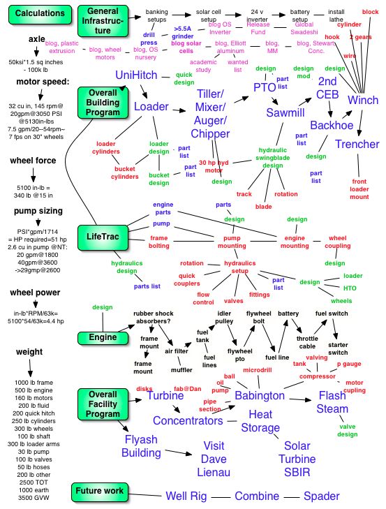
As of 5.24.08, the current working program surrounding LifeTrac is:
Articulated Tractor Design
After examining the function of skid-steering, we decided to add articulated steering with a 2-degree of freedom flexible coupler. The tractor can both bend and rotate around the middle joint. This allows the tractor to minimize impact on the ground when turning. It also allows all 4 wheels to remain on the ground in uneven terrain - where otherwise it is likely that 1 wheel is off the ground often in uneven terrain.
Initial LifeTrac design is updated here:
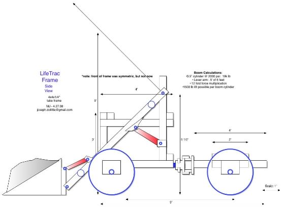
Basic Frame
Here is the basic frame concept, made of 4x4x1/4" tubing.
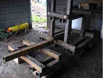
Here is the frame in practice, starting to be bolted together:
You can see our blog for additional information.
Other 2D Drawings
See LifeTrac 2D Drawings for other views.
Engine, Wheel, Hydraulics Addition
Engine
Power plant selection will depend on intended fuel source.
A number of different fuel sources, which could be produced at a local scale, could be utilised.
Pure plant oils
Oil plants can be grown and using simple technologies the oil extracted and used directly as fuel. A compression ignition (diesel) engine of suitable design is required to allow reliable operation with PPOs.
Biodiesel
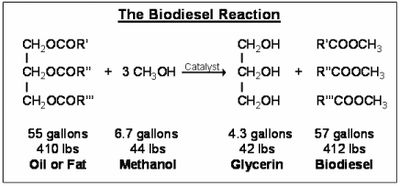
Biodiesel is a fuel made from plant or animal oils. It involves chemically modifying the oil so as to give it properties more closely resembling diesel fuel. Glycerol is a "waste" product that is generated in abundance but it has many uses, so not a problem.
Biogas
Biogas is produced by the anaerobic fermentation of biomass. It can be used to fuel spark ignition engines or as the main fuel source for compression ignition engines which use a small charge of oil to begin each combustion event. (System for biogas and heat production from woody biomass).
Ethanol
Ethanol is produced through alcoholic fermentation of sugars. Strength is increased through distillation.
OBED Open Biofuel Engine Development wiki page detailing biofuels
Loader Addition
Hydraulics Design
Design Rationale
Several aspects must be considered:
- Wheel Motor Control
- Turning Cylinder
- Loader
- Auxiliary Hydraulics
Wheel Motor Control
A 50/50 flow divider is recommended to make sure that if the front wheels come off the ground with the loader, the back wheels still have adequate flow. Without using a divider, the wheels that come off the ground will spin fast and back wheels will stop - because hydraulic fluid takes the path of least resistance.
One way to address this is with a 50/50 rotary flow divider. Expensive option - such as this 21 gpm divider from Surpluscenter - [[2]]
What are alternative routes? What about a simple adjustable flow control valve?
Would a 50/50 flow divider work - [[3]]
Schematic
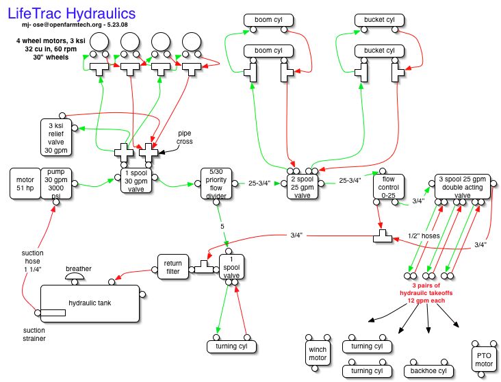
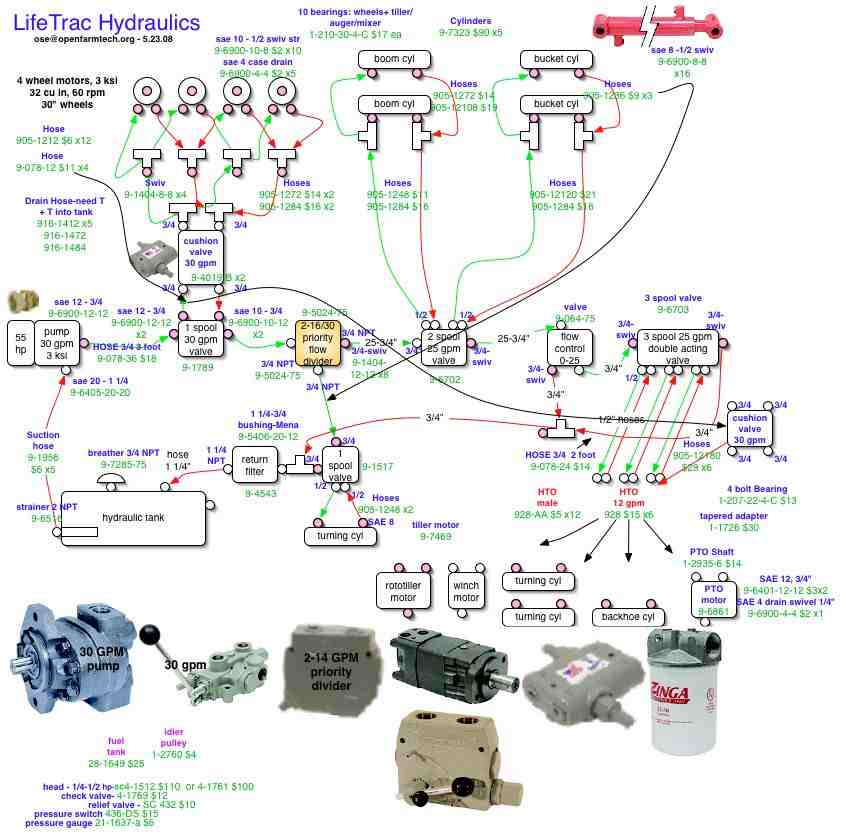
Here is a schematic for the hydraulic power system:
Hydraulics Part Sourcing
Here are some of the part numbers from Surplus Center:
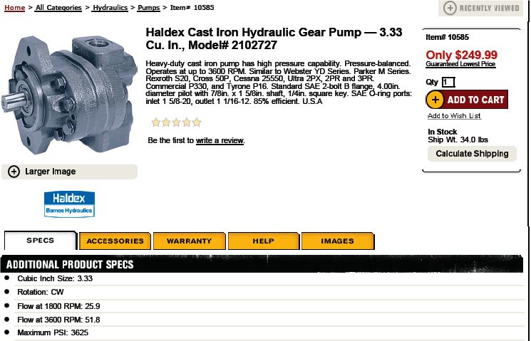
Detail of hydraulic pump from Northerntool - [4] - and calculations -
Hydraulic Pump
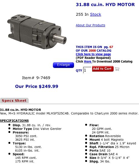
Hydraulic Motors
These are used on each of the wheels and on the rototiller:
Calculations
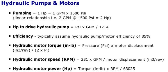
- 1800 RPM gives 26 gpm, so 2000 rpm engine speed of the Deutz 55 hp diesel yields 29 gpm, at a max of 3300 PSI.
- From Surpluscenter tech support, [5] - we have:
- Calculating engine power requirements for the above pump, we have PSI*GPM/1714=3300*29/1714 = 56 hp - or we won't get absolutely high 3600 PSI, but only 3300 PSI, which is still sufficient for any applications.
Hydraulics Implementation Steps
The first step of hydraulics implementation is the wheel drive circuit. This includes the hydraulic pump coupled to the engine, the hydraulic reservoir, wheel motors, control valve, cushion valve, hoses, and hydraulic return line filter. Before the main control valve is activated for driving the wheels, we test the pump by observing proper hydraulic fluid circulation back to the hydraulic reservoir. As a safety measure, the wheels are lifted off the ground, to oberve correct direction of motion of each wheel.
Wheel circuit:
Test procedure:
- Connect hydraulic pump, main wheel control valve, cushion valve, return filter, hydraulic reservoir.
- Turn on engine, observe flow through tank
- Connect wheel motors
- Disengage motors from wheels or lift wheels off ground, and test wheel motors
- Observe correct forward and reverse motion
- Connect steering cylinder, priority flow divider, and steering cylinder valve
- Drive the tractor on even ground and test steering
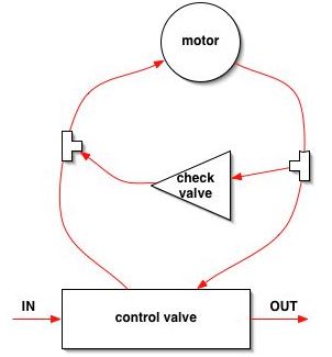
Cushion Valve Plumbing
From part 9-4019-B documentation:
PTO Motor Connection
Post to hydraulics-pneumatics forum
http://forums.hydraulicspneumatics.com/eve/forums/a/tpc/f/8641063911/m/5881043582
Posted 24 May 2008 08:37 PM Hello,
I am looking for suggestions on the design of the hydraulic system for an articulated tractor/loader that I am building.
Please view the hydraulics design. This includes a 55 hp diesel engine, and a series circuit. The circuit includes: (1), 4 reversible wheel motors for the drive; (2), double-acting turning cylinders for articulated steering; (3) front-end loader circuit; (4) 3 pairs of hydraulic take-offs with 12 gpm quick connects. See:
http://openfarmtech.org/index.php?title=LifeTrac#Hydraulics_Design
Please let me know if the design looks sound. In particular:
1. Is this a sufficient pressure release for protecting the wheel motors: http://www.surpluscenter.com/item.asp?UID=2008052417204...35&catname=hydraulic
2. Is it better to do an adjustable priority valve: http://www.surpluscenter.com/item.asp?UID=2008052417204...50&catname=hydraulic or a fixed flow control valve: http://www.surpluscenter.com/item.asp?UID=2008052417204...-5&catname=hydraulic for the first divider in the circuit?
3. If I have a 24 gpm flow requirement for a load at the hydraulic takeoffs, is it ok to utilize two takeoffs to feed into one load? I am looking to run a 24 gpm reversible motor, with 12 gpm per takeoff channel.
4. Is the 0-25 gpm flow control valve: http://www.surpluscenter.com/item.asp?UID=2008052417204...75&catname=hydraulic suitable for controlling the amount of flow to the hydraulic takeoffs?
Marcin
REPLY: Margin;
This forum is mainly frequented by persons in the Industrial Hydraulic & Pneumatic field.
Try your request at one of these sites:
http://www.machinebuilders.net/forum
http://www.hydraulicinnovations.com/forum
Bud Trinkel
FP Consultant Retired
Post to Hydraulic Innovations
This is my hydraulic circuit for a hydraulic, 4-wheel, articulated tractor:
http://openfarmtech.org/index.php?title=Image:LifeTrac_hydraulics.jpg
Is the priority flow divider and flow control valve, plus pressure relief valve for the wheels, sufficient to regulate the flow/prevent overpressure?
I am using:
1. Pressure release for wheel motors: http://www.surpluscenter.com/item.asp?UID=2008052417204...35&catname=hydraulic
2. If I have a 24 gpm flow requirement for a load at the hydraulic takeoffs, is it ok to utilize two takeoffs to feed into one load? I am looking to run a 24 gpm reversible motor, with 12 gpm coming from each takeoff channel.
Marcin
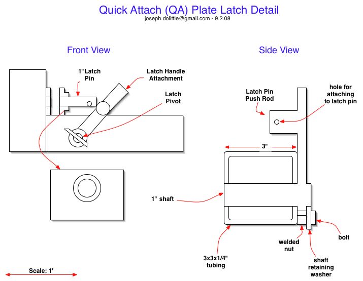
Quick Attach Plate
Proposed Version
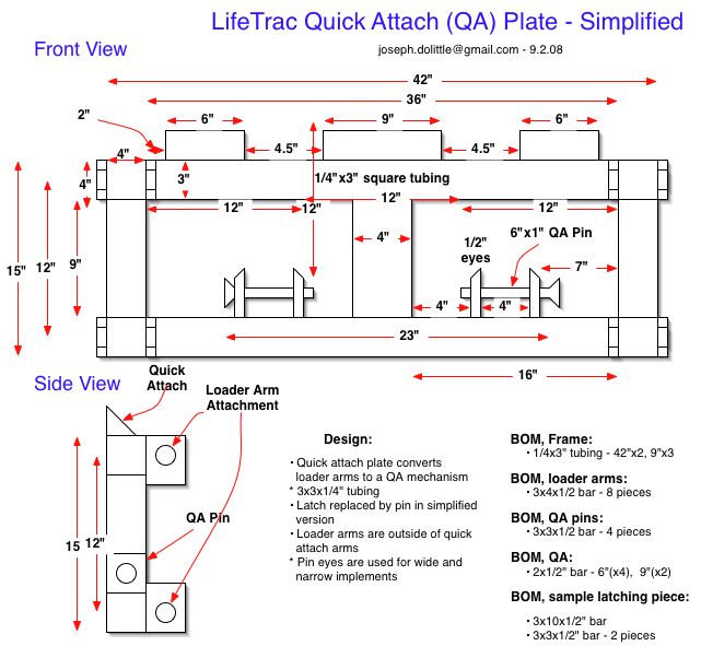
The Quick Attach Plate converts the loader arms to a quick release mechanism for attachments.
Implemented Version
Here is an easier version, with pins replacing turnable latches. This is the first implementation:
Rototiller
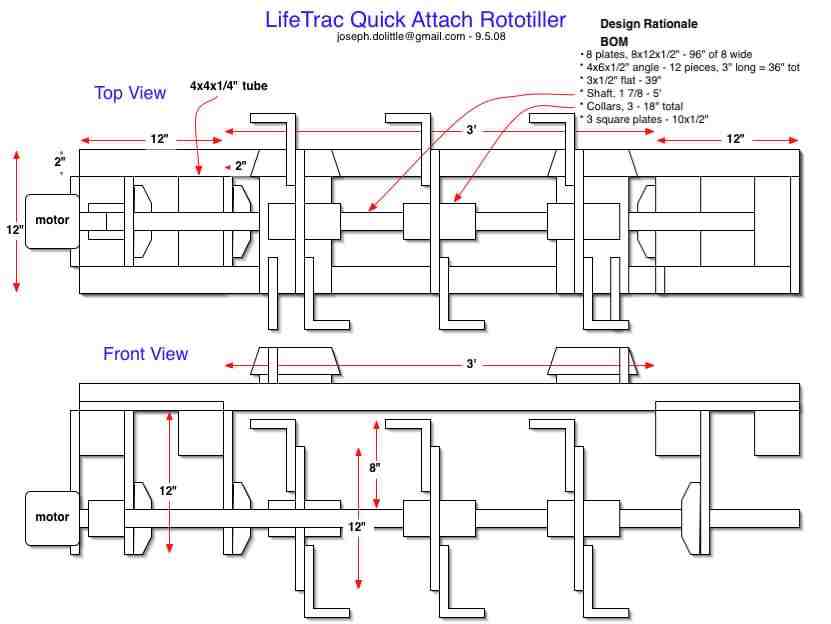
Initial rototiller design:
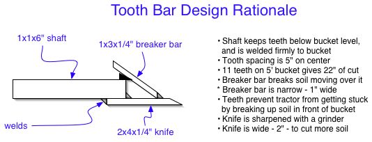
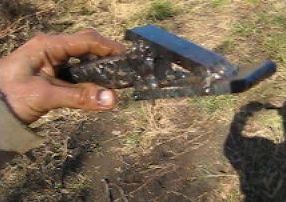
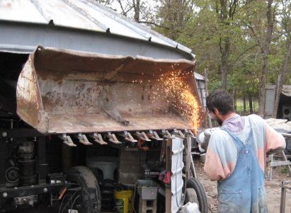
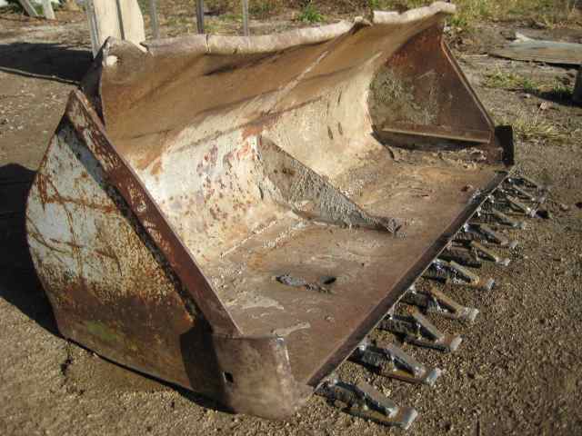
Tooth Bar
Backhoe
Bill of Materials
- Wheels
- Shaft collars, 1-7/8", double split - 4 of them - [6] - $6.75 each
- Tires
- Tire chain quick links, 18 per wheel - 1/4" - [7] - 60 cents each
- Wheel control
- 50/50 divider to allow equal flow to front and back wheels when front wheels come off the ground while doing earth digging with loader - [8] - $88
Bill of Materials for Industrial Counterparts
- One tire and rim - a flat proof one - costs $500 for skid loaders - [9]. Compare to $5 used truck tires with $35 for open source chains - under $50 for a tire. The latter affords the same traction, at 10-100 times less cost, depending if you count the chains or not.
- Which is more cost effective over a lifetime?
- I've heard that you can fill a tire with insulation foam - as a dirt-cheap alternative to professional puncture-proofing gels. Has anyone done this?
I tried this with a small garden cart. My experience was that because insulation foams are non-elastic, once they are compressed, they stay compressed. This would cause a flat spot on your tire each time you hit a rock.
- That makes lots of sense. Similar foams are available with some rubberiness, for e.g. upholstery.
The tyres of most Elevated work platforms are foam filled. Brand names Genie, JLG. They are sealed with a 3/8 (10mm) bolt. I presume the tyre needs to be sealed while the foam goes off
Attachments on Other Machines
- Dingo attachments - [10]
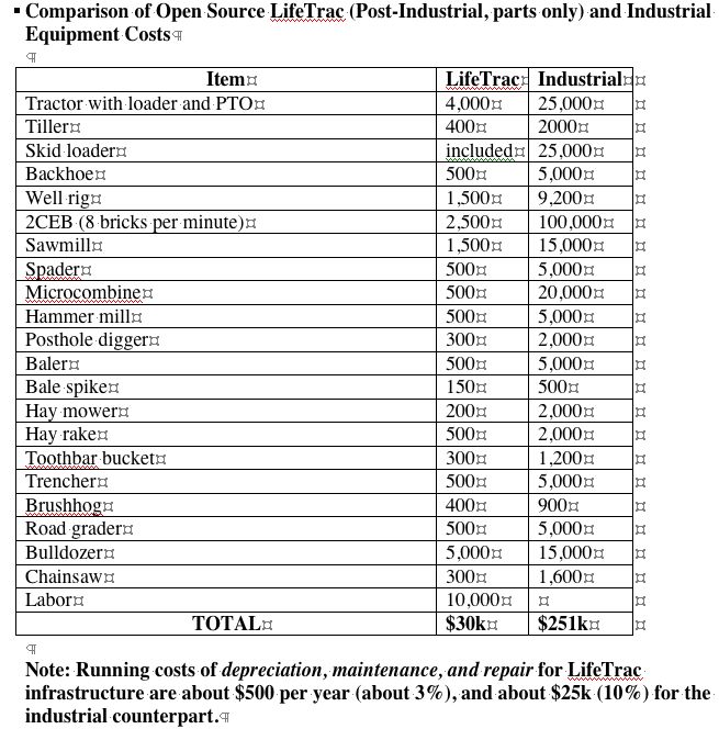
Cost Comparisons to Industrial Counterparts
- NOTE: Industrial prices are taken largely from Northern Tool catologue - [11] - your local, global supply chain.
- Commercial hydraulic rotary well drilling rig quote - [12]
- Note: Tractor and Bulldozer add up to $9k, for an infrastructure that shares wheel motors, controls, and Power Cubes. Power Cubes are $1750 each for 27 hp using off-shelf components. For about 100 hp of drive, this is $7k.
- Note: Since Power Cubes are not included here, the real cost of the package should be closer to $40k for the GVCS implementation prior to the ability to melt steel into virgin metal. This ability, combined with advanced CNC machining, will bring the cost down to about $5000 for 50,000 lbs of steel obtained from scrap sources.
- Note: Each device takes on average 1 week to fabricate after optimization to digital fabrication. This implies a total labor time of about 20 weeks for the devices above, or only $15/hour at the labor cost given. This may be acceptable for DIY value, but is a low rate for market production.
Outstanding Tech Questions
Horses
In terms of biofuels conversion, horses may be far more efficient than tractors. In no-till or low-till permaculture farming with local fuel production, tractors might not make sense at all. http://www.lowtechmagazine.com/2008/04/horses-agricult.html
Response
One would have to do more careful, side-by-side analysis on the above. A horse, whether used or not, eats the equivalent biofuel crop for 1 gallon of liquid fuel every day. A tractor, on the other hand, eats zero gallons of fuel when it is not used.
