D3D Extruder: Difference between revisions
Jump to navigation
Jump to search
(→BOM) |
(→BOM) |
||
| Line 9: | Line 9: | ||
=BOM= | =BOM= | ||
<html><iframe src="https://docs.google.com/spreadsheets/d/1WNRJfb56ilHlIcdcz5cS92sy0QnUK5MiNVzNW1Jf7Lc/pubhtml?widget=true&headers=false" height=400 width= | <html><iframe src="https://docs.google.com/spreadsheets/d/1WNRJfb56ilHlIcdcz5cS92sy0QnUK5MiNVzNW1Jf7Lc/pubhtml?widget=true&headers=false" height=400 width=650></iframe></html> | ||
[https://docs.google.com/spreadsheets/d/1WNRJfb56ilHlIcdcz5cS92sy0QnUK5MiNVzNW1Jf7Lc/edit#gid=0 edit] | [https://docs.google.com/spreadsheets/d/1WNRJfb56ilHlIcdcz5cS92sy0QnUK5MiNVzNW1Jf7Lc/edit#gid=0 edit] | ||
Revision as of 03:28, 24 May 2017
Versions
- D3D first version - MK8 extruder - File:D3D Extruder.fcstd
- D3D second version - Prusa i3 MK2 Original - OSE Adapted - Extruder - File:Prusa i3 mk2 extruder adapted.fcstd
BOM
CAD File Downloads
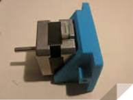
Simple Extruder Holder
- FreeCAD -File:Motor interface.fcstd. I used M4 nuts for the nut catcher, but for the screws I used added the https://www.mcmaster.com/#90116a217/=14gcc4s that are already in the universal axis, in order to avoid adding a new item to the BOM
- STL - File:Motor interface.stl
Working Document
Development Document
BOM
- Use this extruder - [1]
Exploded Part Diagram
Part Files
3D Printed
- Extruder Idler - File:Idler.stl - File:Idler.fcstd
- Extruder carriage side - File:Carriage side.stl - File:Carriage side.fcstd
- Extruder motor side - File:Motor size.stl File:Motor side.fcstd
Other Parts
- Stepped motor - File:Nema17.stl - File:Nema17.fcstd
- Pulley - File:Pulley.fcstd - File:Pulley.stl
- 8mm bearing - File:8mm bearing.stl - File:8mm bearing.fcstd
- E3D V6 - File:E3Dv6.stl - File:E3Dv6.fcstd
Fasteners
Tech Tree of Choices
We go from Tech tree of choices -> Industry Standards -> Technology Assessment -> Value Proposition
- These are all the different ways to implement an extruder for a 3D printer.
- Hit Ctrl-mouse scroll to zoom in
