D3D CNC Circuit Mill: Difference between revisions
No edit summary |
(Added some info + minor organizational stuff) |
||
| Line 1: | Line 1: | ||
=Basics= | |||
- A CNC mill used for PCB Milling | |||
- Can't make as small of traces as a lithography+ethcing system, BUT it is far cheaper and easier to use (ie no chemical etchants or photoresists needed) | |||
- Uses the D3D Univeral Axis | |||
=Used For= | |||
- [[Open Source Digital Fabrication Construction Set]] | |||
- [[Open Source Electronics Construction Set]] | |||
=September 2017 Update= | =September 2017 Update= | ||
<html><iframe src="https://www.facebook.com/plugins/post.php?href=https%3A%2F%2Fwww.facebook.com%2Fmarcin.jakubowski.378%2Fposts%2F10211757474629506&width=500" width="500" height="468" style="border:none;overflow:hidden" scrolling="no" frameborder="0" allowTransparency="true"></iframe></html> | <html><iframe src="https://www.facebook.com/plugins/post.php?href=https%3A%2F%2Fwww.facebook.com%2Fmarcin.jakubowski.378%2Fposts%2F10211757474629506&width=500" width="500" height="468" style="border:none;overflow:hidden" scrolling="no" frameborder="0" allowTransparency="true"></iframe></html> | ||
=July 2017= | =July 2017= | ||
[[File:d3dmill.jpg|500px]][[File:d3dmill2.jpg|500px]] | [[File:d3dmill.jpg|500px]][[File:d3dmill2.jpg|500px]] | ||
| Line 14: | Line 42: | ||
</html> | </html> | ||
=Development Pictures= | |||
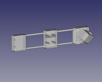
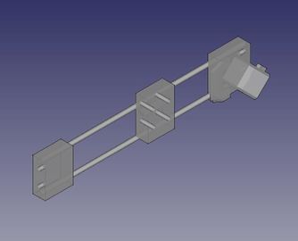
[[File:Circuitboardmill axes disassembly.JPG|frameless|600px|middle|alt=The disassembled axes required to convert the D3D printer to the circuit board mill|The disassembled axes required to convert the D3D printer to the circuit board mill]] | |||
The disassembled axes required to convert the D3D printer to the circuit board mill | |||
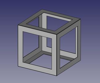
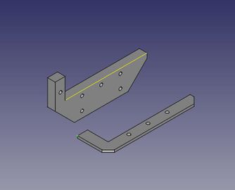
[[File:D3D_Extras.jpeg|frameless|600px|middle|alt=These are the required additional parts to transition from the 3D printer to the circuit board mill|These are the required additional parts to transition from the 3D printer to the circuit board mill]] | |||
These are the required additional parts to transition from the 3D printer to the circuit board mill | |||
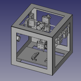
[[File:D3D_Axes.jpeg|frameless|600px|middle|alt=The complete set of axes for the D3D circuit mill|The complete set of axes for the D3D circuit mill]] | |||
The complete set of axes for the D3D circuit mill | |||
=Working Document= | =Working Document= | ||
==Design== | ==Design== | ||
<html><iframe src="https://docs.google.com/presentation/d/1C4IuTWnB4G93zKcHiDYbKnv-I1E9vXXrRzeZbQzTZmM/embed?start=false&loop=false&delayms=3000" frameborder="0" width="960" height="569" allowfullscreen="true" mozallowfullscreen="true" webkitallowfullscreen="true"></iframe></html> | <html><iframe src="https://docs.google.com/presentation/d/1C4IuTWnB4G93zKcHiDYbKnv-I1E9vXXrRzeZbQzTZmM/embed?start=false&loop=false&delayms=3000" frameborder="0" width="960" height="569" allowfullscreen="true" mozallowfullscreen="true" webkitallowfullscreen="true"></iframe></html> | ||
[https://docs.google.com/presentation/d/1C4IuTWnB4G93zKcHiDYbKnv-I1E9vXXrRzeZbQzTZmM/edit#slide=id.g1861bf60d5_0_6 edit] | [https://docs.google.com/presentation/d/1C4IuTWnB4G93zKcHiDYbKnv-I1E9vXXrRzeZbQzTZmM/edit#slide=id.g1861bf60d5_0_6 edit] | ||
==Data Collection== | ==Data Collection== | ||
<html><iframe src="https://docs.google.com/presentation/d/1n4KegLSiURKZQzL4JkHLyYosdQdHT3C8u430TYw3fmI/embed?start=false&loop=false&delayms=3000" frameborder="0" width="480" height="299" allowfullscreen="true" mozallowfullscreen="true" webkitallowfullscreen="true"></iframe></html> | <html><iframe src="https://docs.google.com/presentation/d/1n4KegLSiURKZQzL4JkHLyYosdQdHT3C8u430TYw3fmI/embed?start=false&loop=false&delayms=3000" frameborder="0" width="480" height="299" allowfullscreen="true" mozallowfullscreen="true" webkitallowfullscreen="true"></iframe></html> | ||
[https://docs.google.com/presentation/d/1n4KegLSiURKZQzL4JkHLyYosdQdHT3C8u430TYw3fmI/edit#slide=id.p edit] | [https://docs.google.com/presentation/d/1n4KegLSiURKZQzL4JkHLyYosdQdHT3C8u430TYw3fmI/edit#slide=id.p edit] | ||
=CAD files= | =CAD files= | ||
| Line 46: | Line 107: | ||
File:PCBholder_image.jpeg|PCB holder: [[File:PCBholder simplified.FCStd]] | File:PCBholder_image.jpeg|PCB holder: [[File:PCBholder simplified.FCStd]] | ||
</gallery> | </gallery> | ||
==Accurate Files== | ==Accurate Files== | ||
<gallery mode="packed-hover" heights="180"> | <gallery mode="packed-hover" heights="180"> | ||
File:D3D end stop interface complex.jpeg|'''3x End Stop interface:''' [[File:D3D End stop interface.fcstd]] | File:D3D end stop interface complex.jpeg|'''3x End Stop interface:''' [[File:D3D End stop interface.fcstd]] | ||
| Line 62: | Line 128: | ||
</gallery> | </gallery> | ||
==List of Files== | ==List of Files== | ||
*'''Assembly:''' [[File:D3D_Circuit_Mill.fcstd]] | *'''Assembly:''' [[File:D3D_Circuit_Mill.fcstd]] | ||
*Frame 16" assembled: [[File:Full_Frame_16in.FCStd]] | *Frame 16" assembled: [[File:Full_Frame_16in.FCStd]] | ||
| Line 73: | Line 142: | ||
*Spindle Motor Mount: [[File:D3D Circuit Mill Motor Mount.fcstd]]. STL - [[File:D3D Circuit Mill Motor Mount.stl]] | *Spindle Motor Mount: [[File:D3D Circuit Mill Motor Mount.fcstd]]. STL - [[File:D3D Circuit Mill Motor Mount.stl]] | ||
*''PCB Holder: [[File:d3dcnccm_PCB_holder.stl]] [[File:PCBholder simplified.FCStd]] | *''PCB Holder: [[File:d3dcnccm_PCB_holder.stl]] [[File:PCBholder simplified.FCStd]] | ||
==Design Notes== | ==Design Notes== | ||
Note on CAD Procedure and Organization: | Note on CAD Procedure and Organization: | ||
#Draw a frame piece, and create a complete frame made of 6 of these pieces. | #Draw a frame piece, and create a complete frame made of 6 of these pieces. | ||
| Line 86: | Line 158: | ||
#Save the Z axis file as [[File:D3D Circuit Mill Z Axis.fcstd]]. | #Save the Z axis file as [[File:D3D Circuit Mill Z Axis.fcstd]]. | ||
#Import the | #Import the | ||
=Industry Standards= | =Industry Standards= | ||
*Hackaday projects - [https://hackaday.io/list/6906-cnc-projects] | *Hackaday projects - [https://hackaday.io/list/6906-cnc-projects] | ||
= | |||
=Existing Open Source Designs= | |||
*[[Cyclone PCB Circuit Mill]] | *[[Cyclone PCB Circuit Mill]] | ||
*[[Sienci Mill]] | *[[Sienci Mill]] | ||
= | |||
=See Also= | |||
*[[Universal CNC Axis]] | *[[Universal CNC Axis]] | ||
=Usefull Links= | |||
* | |||
=Discussion= | =Discussion= | ||
<html><div id="disqus_thread"></div> | <html><div id="disqus_thread"></div> | ||
<script> | <script> | ||
Revision as of 08:20, 8 January 2018
Basics
- A CNC mill used for PCB Milling
- Can't make as small of traces as a lithography+ethcing system, BUT it is far cheaper and easier to use (ie no chemical etchants or photoresists needed)
- Uses the D3D Univeral Axis
Used For
- Open Source Digital Fabrication Construction Set
- Open Source Electronics Construction Set
September 2017 Update
July 2017


Development Pictures

The disassembled axes required to convert the D3D printer to the circuit board mill

These are the required additional parts to transition from the 3D printer to the circuit board mill

The complete set of axes for the D3D circuit mill
Working Document
Design
Data Collection
CAD files
Simplified Files
Assembly: File:D3D Circuit Mill.fcstd
D3D frame 16": File:D3D frame assembled 16 inch.FCStd
Single x axis: File:D3D Circuit Mill X Axis.fcstd
Single y axis: File:D3D Circuit Mill Y Axis.fcstd
Single z axis: File:D3D Circuit Mill Z Axis.fcstd
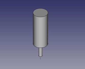
spindle motor: File:T-king spindlemotor.fcstd
Spindle Motor Mount: File:D3D Circuit Mill Motor Mount.fcstd
PCB holder: File:PCBholder simplified.FCStd


Accurate Files
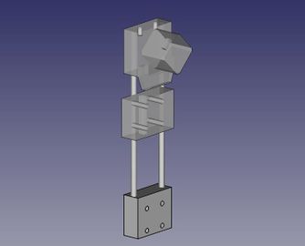
3x End Stop interface: File:D3D End stop interface.fcstd
![16x carriage piece: [[1]]](/images/thumb/6/65/Universal_axis_carriage_side.jpeg/324px-Universal_axis_carriage_side.jpeg)
16x carriage piece: [[1]]
![16x idler piece short: [[2]]](/images/thumb/d/d4/Universal_Axis_Idler_piece_short_complex.jpeg/333px-Universal_Axis_Idler_piece_short_complex.jpeg)
16x idler piece short: [[2]]
![12x motor piece: [[3]]](/images/thumb/9/91/Universal_axis_motor_side_complex.jpeg/324px-Universal_axis_motor_side_complex.jpeg)
12x motor piece: [[3]]
2x Spindle Motor Mount: File:D3D Circuit Mill Motor Mount.fcstd
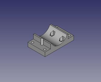
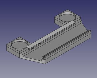
![PCB holder: [[4]]](/images/thumb/6/6d/PCBholderaccurate.jpeg/344px-PCBholderaccurate.jpeg)
PCB holder: [[4]]

![16x carriage piece: [[1]]](/wiki/File:Universal_axis_carriage_side.jpeg)
![16x idler piece short: [[2]]](/wiki/File:Universal_Axis_Idler_piece_short_complex.jpeg)
![12x motor piece: [[3]]](/wiki/File:Universal_axis_motor_side_complex.jpeg)
![PCB holder: [[4]]](/wiki/File:PCBholderaccurate.jpeg)
List of Files
- Assembly: File:D3D Circuit Mill.fcstd
- Frame 16" assembled: File:Full Frame 16in.FCStd
- Single 16" frame: File:Single Frame 16in.fcstd
- Single x axis: File:D3D Circuit Mill X Axis.fcstd
- Single y axis: File:D3D Circuit Mill Y Axis.fcstd
- Single z axis: File:D3D Circuit Mill Z Axis.fcstd
- Spindle Motor: File:T-king spindlemotor.fcstd
- Spindle Motor Mount: File:D3D Circuit Mill Motor Mount.fcstd. STL - File:D3D Circuit Mill Motor Mount.stl
- PCB Holder: File:D3dcnccm PCB holder.stl File:PCBholder simplified.FCStd
Design Notes
Note on CAD Procedure and Organization:
- Draw a frame piece, and create a complete frame made of 6 of these pieces.
- Save file: File:D3D 13" Frame.fcstd
- Begin the design by downloading the X axis - File:D3D 16 Sub-assembly X Axis.fcstd
- Correct the length of the axis to 11" length (for 13" frame - 1" shorter on each side to accommodate mounting on the Y axes). Rotate the axis such that the orientation - when looking according to the Viewing Direction and XYZ axis orientation of Slide 1 in Working Document - is that the motor is on the left side of the axis (note that the orientation shown in First Slide in the Working Document has the motor on the right hand side, which is not correct).
- Save the file as File:D3D Circuit Mill X Axis.fcstd once the length is 11" and orientation is correct. This will be the file you can use later for the x axis (2 of them) to merge into the final assembly - with the second x axis being a mirror image.
- Now create the Y axis according to the orientation convention of the First Slide in the Working Document. This axis should be 13" long.
- Save the y axis file as File:D3D Circuit Mill Y Axis.fcstd.
- Now create the Z axis as in the working document. This axis can be 8" long - as we don't need a lot of z travel.
- Save the Z axis file as File:D3D Circuit Mill Z Axis.fcstd.
- Import the
Industry Standards
- Hackaday projects - [5]
Existing Open Source Designs
See Also
Usefull Links