CEB Press/Manufacturing Instructions/Detroit Fab Lab Solenoid Driver v2
Introduction
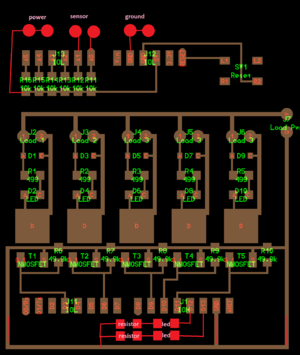
put sensor terminals on detroit board
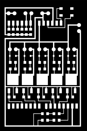
http://opensourceecology.org/wiki/File:Detroit2print.png
http://sketchup.google.com/3dwarehouse/details?mid=10a3722997daf166b38804396e417a9b
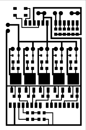
General Processes/Circuit Etching
bug
i found a bug today. there needs to be a connection from the 12v line to the VIN pin next to the ground pin the sensors are connected to. will update drawings when i get the chance. --Dorkmo 21:37, 3 November 2011 (CET)
- k updated --Dorkmo 00:49, 12 November 2011 (CET)
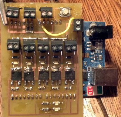
Finished Board
Note: jumper not needed, already corrected in board image for pcb etching.
Upgrades
1
Field testing at Factor e Farm in 2011 has shown that twigs and rocks can jam the soil loading drawer if these are not crushed by the scissor action of the drawer as actuated by 7the secondary cylinder. In the case of a jam, we uploaded the CEB testing code interface to move the drawer by computer control via USB cable. This is time consuming, so the next iteration should include manual bypass toggles on the controller board itself, so the user can mive the drawer manually as needed. This applies to both the primary and secondary cylinder.
To do this, a simple toggle switch such as the reset switch should be placed between the 5V power and the pin corresponding to the left (ejection) motion of the secondary cylinder. This is not necessary for the main cylinder, which has 20 tons of force. This is also not necessary for the right motion of the secondary cylinder, since such motion is already present upon power cycling of the controller.
Implementation
Do we need just a connection to be closed between 5V and the d9 or d10? An?y resistors in between?
2
For full manual testing of hydraulics without using a control computer, 5 of these toggles should be applied, one for each hydraulic channel.


