Bobcat Standard Quick Attach/Research Development
| Bobcat Standard Quick Attach | ||
|---|---|---|
| Home | Research & Development | Bill of Materials | Manufacturing Instructions | User's Manual | User Reviews | 
| |
Status
A version is built at Factor E Farm although it needs some more work.
To Do
- Figure out the problem with mounting the fingers to the tractor at a width that meets the standard. The closest we can get on our 4" grid is 8 holes apart (32" between middles of fingers) but this doesn't quite meet the standard so not all outside equipment will fit on this. This problem may already have been discussed and figured out so look through the work logs first. If there's no great solution there, we probably need a custom mount which holds the fingers the right distance apart and can itself be mounted to the grid. As of Oct 2013, the fingers are mounted 9 holes apart on the LifeTrac 6 and the big bucket and backhoe should work with that.
- Once the tractor-side mounting is figured out, finish modeling it. The model is linked below.
- The tractor side model needs some cleanup. Dan did a rough mirrored finger in the backhoe 2 model but it was hard to do well in part because the model's got some weird geometry.
- The attachment side needs to be modeled in sketchup. There's a draft version of this in the latest backhoe 2 model.
- Take photos of the tractor and attachment pieces and upload them here.
- Field test it.
Sketchup Models
Tractor-side: File:OSEquickAttach.skp. You'd mount one of these on each side of the tractor.
Attachment-side: to do.
Requirement
- Use existing OSE parts (4"x4" box tube, 1/2" plate, 1" bolts, etc).
- Minimize welds, main attachment method bolting.
- Modular so the spacing can be changed according to attachment.
- Conforms to SAE-J2513 standard (File:Sae j2513.pdf).
Developement History
See LifeTrac_Bobcat_Standard and Quick_Attach_Plate_Standard for background on geometry and discussion of ASTM specification of the geometry.
V1
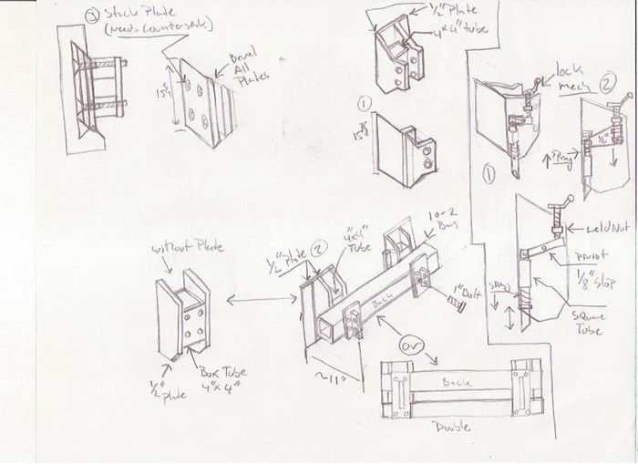
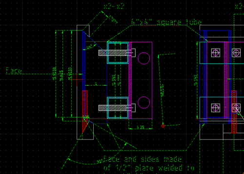
hashed out different design options, made original DXF file.
The drawing shows a reference for multiple designs, the DXF file has the dimensional layout (select layers accordingly, when they are all on it is cluttered).
For the next step it would be good to talk with whomever will fabricate it to lock in the most efficient build based on available parts, especially for the catch mechanism.
Basic layout for quick attach skid steer mech:
V2
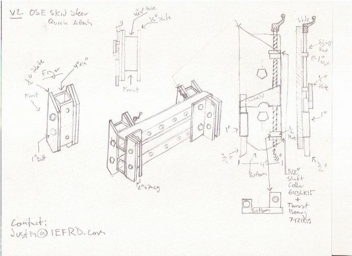
Added in more dimensional work for attachment spacing to skid steer, finished latching mechanism.
Latch mech: The latching mechanism KISSes by utilizing a 5/8" threaded rod that attaches to a 1/2" plate with weld nuts. The plate moves the latch rod to connect and disconnect, this gets rid of any spring or lever which could jam or release during use.
All parts are standard McMaster.
Overview of updated mech:
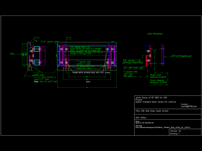
DXF has true dimensions except for 48" spacing of skidsteer plates.
DXF of Critical Component
Links
- See Justin Log


