Shonda Log
sept 30
staked another 10 pads and dug 2 to 6 in
wireless camera SD card http://photojojo.com/store/awesomeness/eye-fi-wifi-memory/
new idea for second generation multimachine. head stock with verical (Y axis) travel and rotation around the Y axis (B axis), this allows for the headstock to be used as a milling head, and with a rotary table (also used for the versamill) the machine will function as a 5 axis machinetool.
sept 29
staked 8 of the hablab concrete piller pads (took ~20 minutes per pad, without water or spirit leveling pads)
=sept 25=00
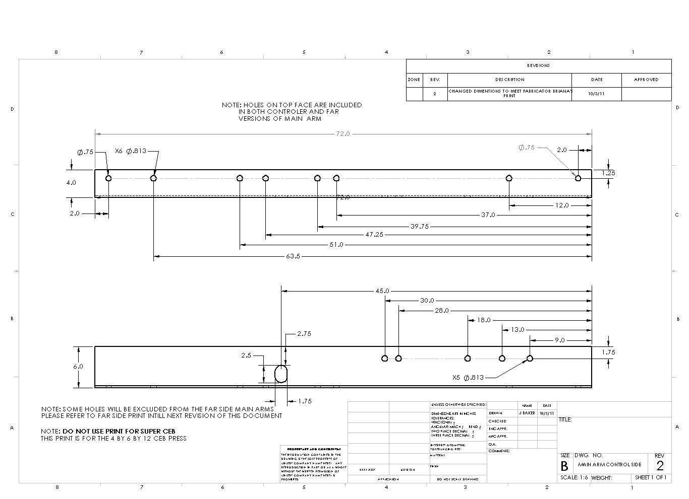
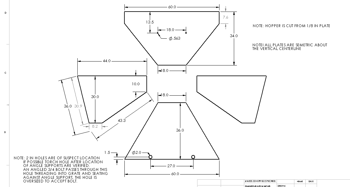
File:CEB hopper.dxf File:CEB main arm.dxf
SEPT 23
sept 22
sept 18
Title of Your Proposal1
by Name and Your Picture; name is linked to your Team Culturing Survey2
Date (9/18/2011)
Jershond@gmail.com
Abstract: – a high level discussion of your deliverable, its economic significance, relevance to addressing pressing world issues, relevance to Distributive Enterprise, its fit within the context of the GVCS, and relevance to the infrastructures of new civilization. Also include a summary of economic analysis and deployment timeline.
A Lathe and milling attachment build using concrete and floating steel capable of producing, with NC, hydraulic pumps, motors, and pistons, steam engine cylinders, valves and pistons. The system should cost under 3000 for the lathe, 1000-2000 for the milling attachment and another 2000-3000 for the CNC conversion(before opensource).
Deliverables – a clear and explicit overview of your deliverables, and overview of the timeline for their accomplishment. Please reserve the timeline section further down for a week-by-week breakdown of your milestone goals. Define a clear start and end points for your overall project, such as, “4 weeks from project approval, which is intended to happen on such and such date” etc.
Include sketches, drawings, CAD, CAE analysis, exploded part diagrams, conceptual drawings and other diagrams wherever possible.
Link to open pario
Table of cost and performance comparison to other industry standards for the same machine. Select 3 other competitors with other diverse solutions.
Haas toolroom lathe has a smaller working area at 24 thousand dollars
Scaling calculations – these are basic calculations relevant to your design, which are also applicable to adapting your design to a different scale of machine
calculations for bending of round ways over length
statics for bed strength and concrete cracking
Systems Engineering Breakdown Diagram – break the concept down into components that need to be developed, and publish in the form of a diagram (see examples). The relevance of this is for the review team to understand the context of your work more clearly, and to define the necessary development points with precision.
Points of construction
spindle
concrete bed
strait and round ways, hardened if possible
brass or cast iron shoes for carriage slide
accurate alignment methods (using a machinists level, and a dial indicator, and only if necessary skilled labor(scraping))
OSE Specifications Assessment – Discuss how your work contributes to modular, lifetime design, design-for-simplicity, design for easy fabrication3, and design for high performance.
The use of a lathe and other machine tools will allow is to construct precision mechanical parts for the rest of the GVCS at cost of materials and hydraulics. Having a OSE standard ofr machine tools will allow for easier documentation for production of precision parts as well as automation of that production.
Resources – list the general resources and infrastructure required for project completion. Discuss both what you can bring to the table and what you would like us to provide. Discuss whether you'd like to spend your development time at Factor e Farm or remotely.
Tools
husky machinists level (accurate to .0001 over 10”) ~$60
dial indicator (.0005 accuracy) ~$10
calipers with .001 accuracy ($20 AS&S or $28 amazon)
basic intelligence
concrete mixing capacity
wooden pole for ramming concrete into mold
hole cutting saws for 3” and 5” holes -or- drill, keyhole saw and half round file
Casting mold
3/4” melanine board for making mold
screws for bolting frame together
pins for making assembly of mold easier
clay for plugging holes (if needed)
mold release agent
non-shrinking grout
place to submerge casting after demolding (7 day curing time for concrete)
pipe for mounting voids , four (4) 3” or 3 1/2” nominal one (1) 5” nominal 400mm long
Materials
Concrete 2-3 cubit yards
rebar for bed reinforcement
3 steel ways of the length of the bed of the lathe
3 steel ways of the length of the cross slide of the lathe
around 100 fasteners embedded into the lathe for mounting locations
lead screws one (1) the length of the bed one (1) of the cross slide
thrust rollers (2) and brass flange bearings (2) for each of the leadscrews
2” nominal pipe for spindle 450mm
4 1/2” nominal pipe housing for spindle 300mm
3 tapered roller bearings 27X60X115 SKF ABEC 5
1” steel plate 8X8 for chuck mounting plate
2 seals 90X115 for oil retention
2 brass or cast iron plain bearings for
3” angle for mounting of shoes
2” angle for aligning ways
Timeline – in as much detail as possible, discuss the milestones you hope to reach on a weekly basis. Typically, a prototype or design takes one month of full time development. Include a Gantt chart of your expected deliverables.
After the requirements of workshop space (8' by 10' at least) and funding arrives, construction of the bed mold can begin as soon as materials are purchased. One week for completion of the initial mold, less once the methods are documented (1-2 people days). Welding of the rebar supports 1 day with a heavy welder. Ramming concrete into the form will probably take 4 – 12 man hours. Then once the mold is set work on the ways, lead screws and spindle will commence.
The spindle requires several parts to either be reamed or lathes on a temporary setup. Spindle requires a skin cut and the one inch plate, which has to be itself bored to the spindles diameter, to be shrunk onto it. Spindle housing pipe has to be bored out on each end 37mm and 64mm respectively, and an oil inlet drilled into the side/bottom. Once the mounting plate is in place mounting spacers, housing, seals and bearing onto the spindle with the use of pairs of split clamps and setscrews. The spindle should still spin freely when fully tensioned.
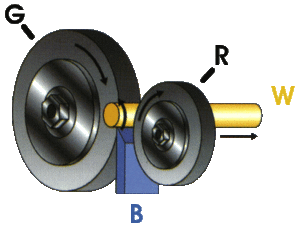
The ways will be ground and lapped to form using a simple jig operated by a geared down motor. Two aluminum plates with a |__/ profile cut into them are mounted on a plate. The three ways are then layed into the jig in a triangle pointing upwards. The bottom two ways are spun by flat belts run off of a 1/4” rod coupled to the geared down motor. One of the belts should be mounted on a collar so that the ways have a differential in speed, allowing grinding to happen. A heavy grinding paste is applied to the ways and they are let to spin until smooth bands on the ways are seen. The ways are then flipped end for end, one at a time until a smooth finish and grinding is noticed along there entire length. Ends should be flipped in a predictable order from first to last. As the grinding continues new, finer abrasives will be used until desired finish is achieved. Once the ways are finished care should be taken to wipe down the entire length to remove any abrasive particles. If the ways begin to take on a hourglass shape along there length, wide at the ends and a narrow waist, then the two end plates supporting the ways are twisted in relation to each other. Printer paper (.003-.004) or other shims can be used to adjust for this twist.
The lead screw bearing assembly is simply a thrust bearing and a brass plain bearing then a flange to mount it onto the lathe with. A micrometer dial and hand wheel can be added for manual operation or a motor for NC.
The cross slide for the lathe is made by an H frame of concrete holding two strait ways. A t slot table will be cast directly into the table using 1/4” X 2” flat stock with bolts welded to the bottom, and plastic channeling
Project Plan – Discuss how you will approach the delivery of the milestones that you outlined in your Timeline.
Budget – Discuss both material costs and your labor/consulting fees. Produce a detailed Bill of Materials for your project, with sourcing information for each part.
Provide sourcing links
Assessment – List the metrics by which you will judge the success of your project, and how these measurements will be made. This is important for clarity on project success/breakdown.
Failure Mode Analysis and Recovery Plan – Discuss the contingencies/dependencies that determine your project success or timeline. Discuss the things that may go wrong in your project, and how you will address these possible breakdowns (budget overruns, performance failures, supply chain issues, team breakdowns, lack of data, etc.). Please perform this analysis on a week-by-week basis for the duration of your proposal.
1Note that you are required to embed this proposal on a wiki page with Your Name Proposal as the title of the page. Embed via HTML export from a text editor, and include an upload of your file in open document format (.odt or similar). Note that this Proposal template refers primarily to machine development. If you are working on documentation, distributive enterprise development, or other organizational issues, all of the paragraphs still apply, though some details (such as exploded part diagrams) may not apply directly to your work.
2The Team Culturing survey is a survey that all developers of the GVCS need to fill out for purposes of team transparency. See discussion here and the actual survey here. The survey is submitted and then appears on the wiki with a page titled John Smith, where the name is your name. Successful project proposals/bids are marked by a thorough job on the team culturing survey. Please don't forget your picture and introductory video. Existing interviews with you taken by the OSE team suffice in lieu of your video.
3Note that easy fabrication refers to the simplicity of design. Simplicity of design needs to be coupled with simplicity of fabrication. We are assuming that we will have a wide range of advanced machines for fabrication and automation - but we are also assuming that we do not add bells and whistles. We believe that performance comes first – but performance is not defined as point-performance of highest power or efficiency – but instead – efficiency from an integrated perfaective that includes human, societal, and ecological factors.
sept 15
budget
sespt 13
tack welded a few pieces, then finished what I could do on the Hydraulic coolers (ran out of parts)
 |
| hydraulic pump |
I pulled apart one of the hydraulic pumps to see the internal structure, the housing parts are made from aluminum and look to be milled, the gears look ground, or just have a very fine finish pass, each of the two mounting blocks have thin brass bushing pressed into them, a gasket seal on the top an bottom plates and a radial seal on the shaft where it exits the pump.
assuming a lathe and versamil with NC control the housings, plates, and sleeve bearings could be made on demand, the gears I have to look into, but a grinding wheel that has been profiled with a diamond could be able to grind them to tolerance if needed. (diamond would be mounted on the collet for holding the gear and the lathe/mill could regrind the wheel when necessary (some testing will be required for determining hoe often the grinding will have to happen))
sept 12
here's a bunch of videos that I cam'ed on sunday, warning, they suck. but they show some of the development.
I also built the model for the MultiLathe, the first revision at least. [File:Lathe first run.JPG|thumb|pic]
vid of [Marcin] moving ythe hay cutter (mower?). yes it is flipped sideways, if you want it the correct direction post a comment on how to flip it, thanks.
sept 5
promises from last week:
- have a 6 month plan for the multimachine project (statues: failed)
- videos for the multimachine project (statues: have to escape them from the black hole)
- Wiki failed to upload Sep.2-3 on muffler
started design of a modified multimachine design, started with the sketchup model
promises for the next week
- model for the MultiLathe
- 6 month proposal skeleton
- dependencies
- videos on the multimachine
design considerations for the multiLathe
- retrofit-ability for CNC
- threading
- main drive (Z-axis), leadscrew or Rack and pinion
- flat slide or round ways for cross slide
- proof of strait way production [Multimachine/Research Development]
Positives:
- Threaded engines
- Cutting of stock for Power Cube
- Grinding for Briana
- Documented track fab
- Drilled all mufflers
ground hopper/shaker motor supports for [Brianna Log]
Promises for week:
- Full frame CAD for Lathe Bed
- Post to Open Pario on a daily basis
- Module list for multimachine project: rotary table, versamil, indexing head, fast spindle, slow spindle, ways, CNC retrofit, toolpost, cross slide, CNC toolchange spindle 40 with air pressure, surface grinder, fly cutting, threading, tap-and-die grinding, possibly cold cut saw, blade manufacturing, ballbearing grinder
- Publish a video describing the modules
surface grinding that i did back at dunwoody. it takes about 1-5 minutes to get a part onto the table and dogs set. the surface of the CEB draws, top, 2 blades, and sides, could be done in 30 minutes to an hour each.
videos of lathe and milling
sept 1
- Threaded engine mounts:
- talked with Bruce most of the morning, possibility of connecting organizations and contacts
- shopping for food
Bruce here through friday not sure how much work I can get done
Aug 31
tried out 123d. verdict: buggy and not yet fully realized, has useful features (sketches w/ constraints, sweeps and revolves etc.) but they are still very hard to use. I wish I had Solidworks, we'll see.
unsure how much work I will be getting done until Saturday, as Bruce will be visiting.
drilling muffler pipe, we have 10 small pipes with 36 1/4" holes
cut
Aug 30
- removed plate from CEB fro rewelding and grinding (also forced nuts onto two plates)
- cut last of stock for Power cubes
- ground CEB press cavity? square
Aug 29
cut angle for the power cubes 1 24”, 2 27”, 4 29”, 8 4.5”, and 4 8” left
ran ad-hoc operations for Briana
found out that the track welding jig was sized for different chain gauge
Aug28
editor and slow internet ate this post
Aug 27
editor and slow internet ate this post
aug 26
- started fleshing out tool dependency for multimachine and related projects. Shonda_Research
- published about 200 track sections
- should do a large drawing (semi promise)
- marked out locations to weld bolts, will have to grind off because to much hang over. increasing bearing distance (not that great of a solution and I can only move it 1.5 inches in further but better then the hang over that I had.)
aug 25
- pinned coupler to drive shaft for lathe, drilled out set screw land, marked out size to torch back bearing plate.
- researched and conversed with multimachine yahoo group
aug 24 2011
- I have been looking through the documentation for the new multimachine lathe and have been trying to up-size it and increase the robustness of the design.
the basic idea is to build a lathe from concrete and round pipe, aligning everything with setscrews and non-shrinking grout. In places without machine shops the lathe can boot strap itself with car parts scroungable from a junk yard.
as we are trying to increase production speed of the prototype I am looking at sourcing major components from outside machiniest, namely the rails (which we could harden and grind with a centerless grinder and induction furnace), and components for the cross slide and tailstock, which will probably be farmed out to sweiger if they have the equipment or a shop in st Josephs. All alignment and casting of the machine will be done onsite however.
currently using L Yoeman's style of concrete and round way machine tools the only imperative tooling is a centerless grinder for making the rails round and strait.
- tolerences of industrial equipment
"Lengths up to 55'
Diameter tolerances to .0002 in
Surface finishes to 4 micro inch." source http://www.centerlessgrind.com
- A vitrified grinding wheel has a max RPM or 3600 generally, a 4000 RPM spindle is fairly easy to make if you can purchase bearing and turn a housing (probably want seals to if its for grinding)
http://groups.yahoo.com/group/multimachine/message/14722
aug 23
got up at 8 so only 4 hours sleep.
tightened wheels on new millermatic.
wood gasifier open source kit [[1]]
horizontal milling machine in previous post not going to work machine is built for facing pieces not tool room work the z axis has about 2 1/2in of travel rather then 12 or more inches that would be useful, also most of the controls are hydraulic with dogs rather then hand cranks.
multimachine groups lathe animation[[2]] shaft fitting bearing plates still need to weld set screw nut on will mark location on.
going to be helping Briana with punching CEB piston holder holes.
promise: 6 month plan for the Multimachine project by 8/25/11
Looked through yahoo Multimachine groups lathe documentation[[3]]. 2 hours. I think they are still missing documentation on lots of theings but they have an open review where people will be asking questions and filling that stuff in ... I'm going to use this as the basis for our lathe project. using hardened and ground shafting rather then scrap pipe, and using a half round slides, that can be bored on a lathe, on the round ways rather then angle Iron and brass wear strips.
other thoughts: add mounting bolts for quick change gearbox (to be added after the lathe is running). bolt down second cross slide plate to first from the bottom. move z axis hand wheel from between ways to side of cross slide using sprocket and chain. flip hub on threading attachment so that sprockets could be quickly changed(maybe, might be more trouble then its worth..
aug 22
internet was out in the morining, it apears that mice use the power switch as a foot hold for getting to the ceiling
revived message from multimachine group (log in Multimachine/Research Development)
worked on lathe motor mounting plate holes were offset. still need to weld 4by4 pipe and motor quick attach plate on. possible difficulty, coupler for motor and 1 7/8 shaft.
helped adam with box blading new workshops site. boxblade quick attach plate started breaking apart and we had to torch bolts off since they were bent then weld a new plate with smaller hole so that the blade wont rip out of the quick attach holder.
spent a 3 hours box blading the site then the second bolt plate ripped out and we brought the tractor back.
my power cord for my computer should be at the post office as of this morning
put up eves on shed roof with adam
found this horizontal milling machine [[4]]
picture from Adam_Log and Tom_Log
put up roofing with Marcin and Briana until 3:30 AM
aug 21
researched concrete machine tools - result - multimachine group is closer then I origenaly thought to releasing designs for a lathe design
helped Adam unstick tractor from second entry way and then moved wood from the chestnut tree to chip pile and wood pile. put up one level line for the workshop.
