Rototiller/Manufacturing Instructions/Shaft and Motor Frame: Difference between revisions
Jump to navigation
Jump to search
No edit summary |
|||
| (6 intermediate revisions by the same user not shown) | |||
| Line 16: | Line 16: | ||
! align="center" |'''QTY.''' | ! align="center" |'''QTY.''' | ||
|- | |- | ||
| Flat|| 0.5" x 2 x 4.25 || align="center"|2 | | Flat|| 0.5" x 2" x 4.25" || align="center"|2 | ||
|- | |- | ||
| Flat|| 0.5 x 8 x 12 || align="center"|3 | | Flat|| 0.5" x 8" x 12" || align="center"|3 | ||
|- | |- | ||
| Rectangular Tubing|| 2" x 4" x 1/4"Thick || align="center"|1 | | Rectangular Tubing|| 2" x 4" x 1/4"Thick x 56"|| align="center"|1 | ||
|} | |} | ||
| Line 30: | Line 30: | ||
! align="center" |'''QTY.''' | ! align="center" |'''QTY.''' | ||
|- | |- | ||
| align="center" |1 || [[ | | align="center" |1 || [[:file:100523.JPG| Cross Tube]] || align="center"|1 | ||
|- | |- | ||
| align="center" |2 || [[ | | align="center" |2 || [[:file:100524.JPG| End Plate, Cross Tube]] || align="center"|2 | ||
|- | |- | ||
| align="center" |3 || [[ | | align="center" |3 || [[:file:100525.JPG| Plate, Motor End]] || align="center"|1 | ||
|- | |- | ||
| align="center" |4 || [[ | | align="center" |4 || [[:file:100526.JPG| Plate, Bearing]] || align="center"|2 | ||
|} | |} | ||
| Line 46: | Line 46: | ||
! align="center" |'''QTY.''' | ! align="center" |'''QTY.''' | ||
|- | |- | ||
| [[ | | [[:file:100522.JPG| Front Holder Welded Assembly]] || align="center"|1 | ||
|} | |} | ||
# Cut piece parts as per part drawings | # Cut piece parts as per part drawings | ||
# Weld end plates onto rectangular cross tube | # Weld end plates onto rectangular cross tube | ||
# Weld motor end plate and two bearing plates as per assembly drawing. Ensure each is welded strongly all around | # Weld motor end plate and two bearing plates as per assembly drawing. Ensure each is welded strongly all around and that they are all parallel to each other | ||
Latest revision as of 21:12, 23 December 2011
| |||||||||||||||||||
Overview

|
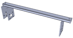
The shaft and motor frame supports the main shaft with the tines and provides a mounting location for the motor. |
Tools Required
Materials Required
| TYPE | SIZE | QTY. |
|---|---|---|
| Flat | 0.5" x 2" x 4.25" | 2 |
| Flat | 0.5" x 8" x 12" | 3 |
| Rectangular Tubing | 2" x 4" x 1/4"Thick x 56" | 1 |
Parts List and Drawings
| ITEM NO. | PART NAME | QTY. |
|---|---|---|
| 1 | Cross Tube | 1 |
| 2 | End Plate, Cross Tube | 2 |
| 3 | Plate, Motor End | 1 |
| 4 | Plate, Bearing | 2 |
Fabrication and Assembly Instructions
| Assembly Name | QTY. |
|---|---|
| Front Holder Welded Assembly | 1 |
- Cut piece parts as per part drawings
- Weld end plates onto rectangular cross tube
- Weld motor end plate and two bearing plates as per assembly drawing. Ensure each is welded strongly all around and that they are all parallel to each other