Dave Log: Difference between revisions
Davepreiss (talk | contribs) |
Davepreiss (talk | contribs) |
||
| Line 32: | Line 32: | ||
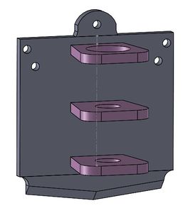
When I went to simplify I found this otherworldly cube mounted between the spindle arms; It could be a clue as to what all that bizarre geometry is for. Deleting it outright causes some real confusion with mates and how those arms were distanced from each other so for now I will just suppress all of its features (as well as the spindle assembly). | When I went to simplify I found this otherworldly cube mounted between the spindle arms; It could be a clue as to what all that bizarre geometry is for. Deleting it outright causes some real confusion with mates and how those arms were distanced from each other so for now I will just suppress all of its features (as well as the spindle assembly). | ||
[[File:OldSpindleWithCube.jpg]] | I was able to get into the "master" sketch for the 3 arms and simplified them a lot. Not sure if I should/can make them taper down. It isn't entirely necessary but aesthetically it would be nice and would cut down on material. | ||
[[File:OldSpindleWithCube.jpg|x300px]] | |||
==Mon Jul 29, 2013== | ==Mon Jul 29, 2013== | ||
Revision as of 17:43, 31 July 2013
- Please coordinate between Dave Log ,John Log, Leo Log, Tim Log, and Nate Log - all work related to HydraFabber.
Wed Jul 31, 2013
HydraFabber
Here's the first ready to print model of the complete carriage. Some concerns that still exist are:
1) How will the software (netfabb/slic3r/cura) react to all the suppressed geometry in the Solidworks file.
2) Also how will said software react to parts being mated adjacent to each other but not actually joined.
3) Lucas brought up a good point: from a physical standpoint is the footprint of the spindle mounts sticking off of the carriage too small? How much force will be exerted on them during the milling process?
Only time will tell!
Tue Jul 30, 2013
HydraFabber
Here's the Taz's spindle assembly. The carriage from yesterday with a quick attatch will replace the blue vertical carriage on the back of this model.
Goals include simplifying the geometry of the 3 arms holding the mill (not sure what all those slots are for). Removing the cross shaped screw holes at the back of the model as our carriage will be printed as one solid piece.
When I went to simplify I found this otherworldly cube mounted between the spindle arms; It could be a clue as to what all that bizarre geometry is for. Deleting it outright causes some real confusion with mates and how those arms were distanced from each other so for now I will just suppress all of its features (as well as the spindle assembly).
I was able to get into the "master" sketch for the 3 arms and simplified them a lot. Not sure if I should/can make them taper down. It isn't entirely necessary but aesthetically it would be nice and would cut down on material.
Mon Jul 29, 2013
HydraFabber
Imported the spindle carriage STL files into Solidworks as solid bodies (not graphic!) and began copying geometry: dimensions and key hole placement.
Extruded a rectangle over the quick attach and used the combine (subtract is inside combine) command to create the male quick attach part.
Combined and mated everything in an assembly. Not sure how simply mating the two parts will interact with being written into G-code as they are technically not connected, but maybe this won't be an issue or will just get resolved by netfabb when we go to print. Also wasn't sure how having the old carriage hidden in the back of the assembly would react to being 3D printed so I made a large extruded cut over it (couldn't delete it due to dependent geometry). Update: This actually caused some errors so I deleted the extruded cut feature and left the rectangular sketch. If you want to see the problem go to the "Imported1" feature and un-hide it.
Here's the Carriage:
Other
Also worked on Current State July 2013 to asses/standardize the GVCS build process with staff and DPVs.


