CNC Torch 1708: Difference between revisions
Jump to navigation
Jump to search
| Line 35: | Line 35: | ||
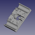
File:CNC_Torch_1708_Motor_interface.png|[[File:CNC_Torch_1708_Motor_interface.fcstd]] | File:CNC_Torch_1708_Motor_interface.png|[[File:CNC_Torch_1708_Motor_interface.fcstd]] | ||
File:bolts.png|[[Bolt_socket_*****.fcstd]] | File:bolts.png|[[Bolt_socket_*****.fcstd]] | ||
File: | File:Hex_nut_0.25.png|[[Hex_nut_0.25.fcstd]] | ||
File:Nema_17_stepper_motor.png|[[File:Nema_17_stepper_motor.fcstd]] | File:Nema_17_stepper_motor.png|[[File:Nema_17_stepper_motor.fcstd]] | ||
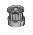
File:GT2 pulley.png|[[File:GT2 pulley.fcstd]] | File:GT2 pulley.png|[[File:GT2 pulley.fcstd]] | ||
Revision as of 03:37, 16 August 2017
- 1"_Universal_Axis deprecated
Version 3 Working Doc
Parts Library / CAD
- CNC Torch 1708 CAD.png
Frame
Rail System
Modules / Individual Parts
- Bolts.png
Torch
Electronics
Various Pictures
====Pins from TB6600 to arduino mega for X axis:
- All 3 negatives (ENA-, DIR-, PUL-) from TB6000, bridged and connected to GRN on Arduino
- ENA+ connected to Pin38
- DIR+ to A1
- PUL+ to A0
====Pins from TB6600 to arduino mega for Y axis:
- All 3 negatives (ENA-, DIR-, PUL-) from TB6000, bridged and connected to GRN on Arduino
- ENA+ connected to PinA2
- DIR+ to A7
- PUL+ to A6


