Dave Log: Difference between revisions
Davepreiss (talk | contribs) |
Davepreiss (talk | contribs) |
||
| Line 61: | Line 61: | ||
'''HydraFabber''' | '''HydraFabber''' | ||
[[File: | [[File:X_Carriage]] (carriage with holes/dimensions) | ||
[[File: | [[File:X_Carriage-qG]] (female quick attach) | ||
Imported the spindle carriage STL files into Solidworks as solid bodies (not graphic!) and began copying geometry: dimensions and key hole placement. | Imported the spindle carriage STL files into Solidworks as solid bodies (not graphic!) and began copying geometry: dimensions and key hole placement. | ||
Revision as of 23:02, 1 August 2013
Please coordinate between Dave Log ,John Log, Leo Log, Tim Log, and Nate Log - all work related to HydraFabber.
Thur Aug 1, 2013
The printing process is underway: see update after #2 from yesterday.
Real progress with the latest print:
Wed Jul 31, 2013
HydraFabber
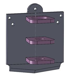
Here's the first ready to print model of the complete carriage. Some concerns that still exist are:
1) How will the software (netfabb/slic3r/cura) react to all the suppressed geometry in the Solidworks file (this was resolved we deleted all the excess parts).
2) How will said software react to parts being mated adjacent to each other but not actually joined. (resolved by John in Solidworks, during the export to STL process, enter options and check both "Save all components in a single file" and "Check for interfaces")
Update: This was not actually resolved, when we went to print the quick attach was printed as its own distinct piece: The solution was to use the join command in the Solidworks assembly which we will use for round 2. This problem is shown in the picture below where the arms are purple and there is a line between the plate and quick attach, but has since been resolved. Now we will look for another method of doing this in Sketchup for the opensource community.
3) Lucas brought up a good point: from a physical standpoint is the footprint of the spindle arms sticking off of the carriage too small? How much force will be exerted on them during the milling process? An easy fix would be to add wings to the arms or fillet the arms to the plate.
4) I kept the distance from the top of the vertical plate to the topmost arm the same as the old spindle mount, but I am not sure how the addition of the quick attach will affect that (will the milling bit still reach the table?)
Only time will tell!
File:CarriageAssembly2.zip (old geometry was just suppressed not deleted)
File:CarriageAssembly3.zip (this file is composed of different parts so the pieces will be printed adjacent but distinct.
The Printing Process:
Our initial print looked good, although in Cura we forgot to use the "Lay Flat" command , as a result a lot of support structure was generated so we aborted. Followed abruptly by a jam in the Ultimaker (second time this has happened while working with this machine). Followed by an overheating error that registered in the 400 C area. John was able to resolve the error by untangling the thermocouple wires.
We decided to jump back to the taz to see if we could get that working but it is still having bed issues (warped?) and the PLA doesn't stick to it at all.
Tue Jul 30, 2013
HydraFabber
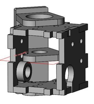
Here's the Taz's spindle assembly. The carriage from yesterday with a quick attatch will replace the blue vertical carriage on the back of this model.
Goals include simplifying the geometry of the 3 arms holding the mill (not sure what all those slots are for). Removing the cross shaped screw holes at the back of the model as our carriage will be printed as one solid piece.
When I went to simplify I found this otherworldly cube wedged between the spindle arms; It could be a clue as to what all that bizarre geometry is for. Deleting it outright causes some minor confusion with mates and how those arms were distanced from each other so for now I will just suppress it (as well as the spindle).
I was able to get into the "master" sketch for the 3 arms and simplified them a lot. Not sure if I should/can make them taper down. It isn't entirely necessary but aesthetically it would be nice and would cut down on material.
Other
Sat in on the Current State July 2013 meeting which moved onto the current state matrix
Mon Jul 29, 2013
HydraFabber
File:X Carriage (carriage with holes/dimensions)
File:X Carriage-qG (female quick attach)
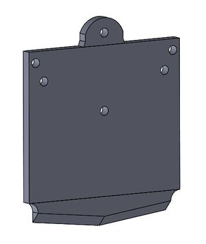
Imported the spindle carriage STL files into Solidworks as solid bodies (not graphic!) and began copying geometry: dimensions and key hole placement.
Extruded a rectangle over the quick attach and used the combine (subtract is inside combine) command to create the male quick attach part.
Combined and mated everything in an assembly. Not sure how simply mating the two parts will interact with being exported back as an STL as they are technically not connected, but maybe this won't be an issue or will just get resolved by netfabb when we go to print. Also wasn't sure how having the old carriage hidden in the back of the assembly would (couldn't delete it due to dependent geometry).
Update: So John was able to fill a serious gap in my Solidworks chops involving properly deleting features and their associated relations. The looming stl. import behind our carriage has been safely deleted, and now I am beginning to delete my fear of Solidworks error messages!
Here's the (outdated) Carriage:
Other
Also worked on <a _fcknotitle="true" href="Current%20State%20July%202013">Current State July 2013</a> to asses/standardize the GVCS build process with staff and DPVs.


