Power Cube/Manufacturing Instructions
| Power Cube | ||
|---|---|---|
| Home | Research & Development | Bill of Materials | Manufacturing Instructions | User's Manual | User Reviews | 
| |
| |||||||||||
Overview

Preparation
Safety
- Hearing Protection
- Eye Protection
- Steel Toe Boots
- Welding
- Gloves
- Hood
- Apron/Jacket
Workspace
- Tables?
- Vice
- Ventilation
Tools
- Welder
- Angle Grinder
- Hand Tools
- Crescent wrench
- Socket set
- Hammer
- Metal Cutting Tools
- Bandsaw
- Chopsaw
- Torch
- Paint Tools
- Gravity Fed Paint Sprayer
- Air compressor
Raw Materials
- Material Name
Hydraulic tank component cleaning prior to welding
- Clean tank edges
- Clean inside of tank
- Clean-grind tank bungs
Subassembly Fabrication
Many of the items listed in the Bill Of Materials require preparation before use in assembly of the Power Cube. This includes drilling and cutting steel up to 3/8” in thickness. These are the parts for assembling a Power Cube.
Engine & Hydraulic Pump mounts
- ¼” x 8” x 12” Plate
- ¼” x 8” x 9” Plate
- ¼” x 2” x 2” x 8” Angle
- ¼” x 2” x 2” x 29” Angle
- ¼” x 8” x 8” Plate

Torching of engine mounts:
Quick attach mounts
- [2] 3/8” x 4” x 27” Plates

Fuel tank
- [2] ¼” x 4” x 8” Plates
- 4” x 8” x 14 ½” Tube
- ¼” x 2” x 24” Plate
- All welds assembling the tank must be quality welds, as they must not leak. Be careful not to “over weld” the tank to the mount.
- Clean the inside of the ¼” x 4” x 8” tube and the two ¼” x 4” x 8” plates – anything left on these surfaces will end up in the gasoline and could clog the engine when started. Tack and weld the plates on each end of the tube, taking care to orient the top plate with the filler hole as shown in the diagram below.
- Weld the 1/4” tank flange to the smaller hole.

Oil Cooler Mount
- [2] ¼” x 2” x 24” Plates
- [2] ¼” x 2” x 1” Plates
- [2] ¼” x 2” x 22” Plates (Note: the holes in these plates may need adjustment based on oil cooler mounting holes)

Key Switches and Choke

- [3] 1/8” x 2” x 2” x 2” Angle

Electrical cables
- Note: The connectors can be purchased from an auto parts store – be aware that they usually require a crimper to attach to the cables. Alternatively, 3/8” copper tubing can be used in 1 ½” long pieces instead. Strip 1 ½” insulation from the cable, fully insert fully into 1 ½” copper tube, flatten end with a hammer and drill hole.

- [2] 11” 1 gauge
- 8 ½” 1 gauge

Battery Mount
- [2] ¼” x 2” x 2” x 4 3/4” Angle
- [2] ¼” x 2” x 5/8” Plate

Hydraulic reservoir
- [2] ¼” x 6” x 12”
- 6” x 12” x 27 ½” Tube
- 2” x 2 ¼” x 1/8” Tube
- All welds assembling the reservoir must be quality welds that do not leak. Be careful not to “over weld” the reservoir.
- Clean the inside of the tube and the two end plates – anything on these surfaces will end up in the hydraulic oil and could damage the pump or cylinders.
- Tack and weld the 6” x 12” plates to both ends of the 6” x 12” tube. Pay attention to the orientation of the plate with the filler hole and the side of the tube with other holes – see the diagram below.

- Tack and weld the strainer extension tube to the tank, centered around the strainer hole.
- Insert the strainer into the flange and insert it into the strainer extension tube – verify that it slides without binding or bottoming and that the flange is flush with the end of the tube. Remove the strainer from the flange, then tack and weld the flange to the tank.
CAUTION: Keep the strainer away from the welding, as its thin wires burn easily.
- Suction strainer, weld-in flange, 2” x 2 ¼” x 1/8” tube:

Assembly
Power Cube assembly requires all the parts listed in the Bill Of Materials to be available and prepared as detailed in the “Fabrication” section (above). Assembly requires a welder (electric or torch) capable of welding metal 3/8” thick.
A Power Cube Jig can be very useful during the welding stage:

Top / Bottom Rectangles
- Position two ¼” x 2” x 2” x 29” pieces angle iron on top of two 27” angle pieces as shown below. Check that all joints are square, then tack and weld joints.

- With one welded rectangle on the bottom, position two 24” pieces outside corner joints as shown below. Check that the angles are square, then tack and weld. Note: The optional jig makes this much easier and accurate. Repeat the prior procedure and this one for another half of the frame assembly.

- Position the two half cubes together, then tack and weld. Inspect all corners to verify secure welds.

Gas tank
- Screw the 1/4" hose barb into the 1/4 NPT flange welded into the gas tank.
- Perform a “soap bubble” test on the tank. Securely cover the larger hole (use something like strong tape), pressurize the tank using the smaller hole and cover the tank surface with soapy water. Look closely for new bubbles, mark any leaks and re-weld securely. Repeat soap bubble test if re-welded.
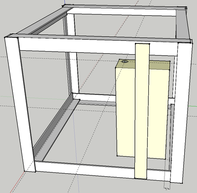
- Tack and weld the gas tank mount (¼” x 2” x 24” plate) to the frame. Position it so the gas tank is 1" from the nearest vertical angle iron support.
- Tack and weld the gas tank to the gas tank mount as shown below.

Hydraulic tank
- Perform a “soap bubble” test on the tank by securely covering the larger hole (use something like strong tape), pressurizing the tank using the smaller hole and cover the tank surface with soapy water. Mark any leaks and re-weld securely. Repeat soap bubble test if re-welded.
- Secure to the frame using 6" clamps, then weld to the frame as shown with 4 1” welds. The tank is ¼” and it can be easily damaged by over-welding. Spacers may be needed on the sides near the top to keep everything snug.

Engine Mounts and Hydraulic Motor Mount
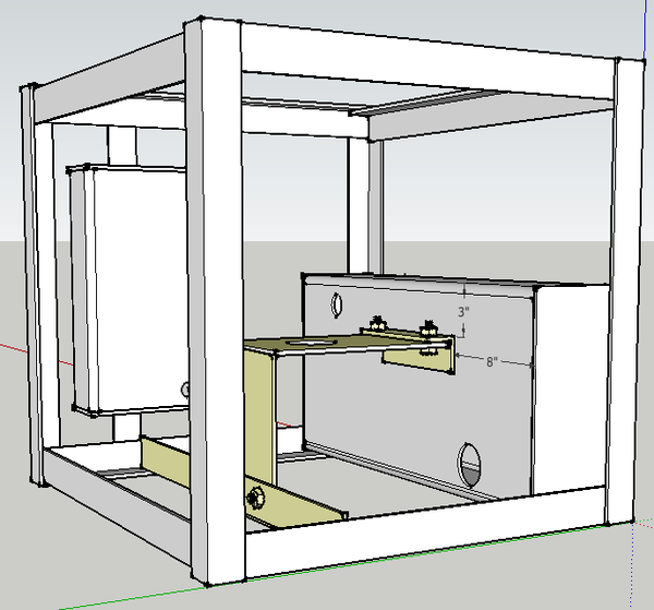
- Position the ¼” x 2” x 2” x 29” angle 10 1/4” from the hydraulic tank (see diagram below). Tack and weld it to the frame.
- Place the ¼” x 2” x 2” x 8” angle against the tank, 2 1/4" below the tank top and with holes aligned with holes in welded angle. Tack and weld to tank.
- Place the ¼” x 8” x 9” plate on the bottom angle iron, align holes and secure with bolts, nuts and washers.
- Place the ¼” x 8” x 12” plate under the 8" angle, align the holes and secure with two bolts, nuts and washers. Align this assembly with the ¼” x 8” x 9” plate in the prior step, then tack and weld the two plates together.
- Engine mounting
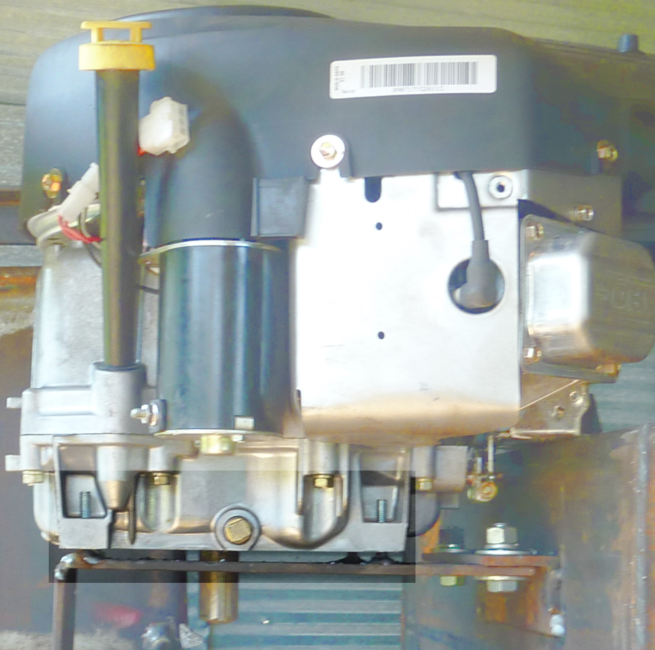
- Examine the engine shaft – it should be 2” long. If longer, cut the shaft to 2” long.
- Hoist the engine and center it on its mounting plate. Verify that the engine shaft extends through the hole without touching the plate.
- Thread nuts on the engine mounting bolts about 2/3 onto each bolt.
- Lift each side of the engine from the plate and insert the four engine mounting bolts in the mounting holes so the engine is supported by the bolts.
- Re-check the engine alignment on the plate, then weld the bolt heads to the engine mounting plate.
- Hydraulic Pump Mounting
- Place the engine key in the engine shaft keyway (it should fit tightly in the slot)
- Slide the larger end of the coupling on the engine shaft
- Tighten the lock screw with the appropriate hex key (ie: allen wrench).
- Bolt the hydraulic pump to the pump mounting plate using two (size) bolts and (size) nuts.
- Thread one nut on each of the four 3/4" x 4 1/2" bolts, insert the bolts through the holes on the hydraulic pump mounting plate as shown below.File:PumpBolts.jpg
- Verify that the key is in the hydraulic pump shaft, then align it with the keyway in the coupler and slide the pump upwards until the bolt heads touch the engine mounting plate as shown below. Tighten the lock screw on the coupling with the appropriate hex key.File:PumpPlateMounting.jpg
- Align the hydraulic mounting plate so its edges are parallel with the engine plate and weld the four 3/4" bolt heads to the engine plate as shown below.File:PumpPlateWelded.jpg


Battery mount
- Weld the ¼” x 2” x 5/8” plates to the ends of the ¼” x 2” x 2” x 4 3/4” plates as shown below.

- Weld the two mounts to the angle iron and tank to form a rectangle for the battery as shown below.*<image>
- After the mount has cooled, lower the battery into the rectangle to verify it fits properly.
Quick Attach Plates
- Weld the [2] 3/8” x 4” x 27” plates to the top sides of the frame as shown. Secure at 45 degree angles before welding in place. Use solid, strong welds the entire length of the plates, as they will bear the load of the entire power cube.

Oil cooler and fan mounts
- Position the two ¼” x 2” x 22” plates to the outside of the frame, adjust so the oil cooler mounting bolts match the holes in the plates and is positioned as in the diagram below. Tack and weld the mounts in to the frame. Verify that the oil cooler bolts match the holes in the mounts.
- Use the mounting holes in the fan shroud and the oil cooler width for positioning the mounting plates as shown in the diagram below. Position the four ¼” x 2” x 1” plates, then tack and weld. Position the two ¼” x 2” x 24” plates against the 1” plates, then tack and weld. Place the fan on the supports and mark the mounts with bolt hole positions. Place the bolt heads against the fan mounting plate and weld in place. Verify that the bolts match the holes in the fan. Inside the frame, adjust the fan position to to position fan shroud ¼” from oil cooler fins. Be careful with radiator as the delicate fins are easily bent and damaged.*
Keyswitch Bracket
- Weld the 1/8” x 2” x2” x 2” angle brackets to the frame in the positions shown below. Note that the keyswitch brackets have larger holes than the choke bracket.
Finish and Painting
- Check all external surfaces for sharp edges and smooth with angle grinder.
- Remove the engine if present and apply a coating of paint.
Solenoid Mounting and Installation
- Weld the solenoid mounting bolts to the hydraulic reservoir as shown below. Once cooled, secure the solenoid on the bolts with two nuts.
Keyswitch and Choke Installation
- Install the keyswitches in the brackets and wire as in the wiring illustration below.
- Secure the choke control in its bracket.
Choke Bracket and installation
- Weld the 1/8” x 2” x2” x 2” angle bracket to the frame in the positions shown below.
- Secure the engine choke knob as shown in the illustration below
Throttle Adjustment
- Use a wire to permanently set the throttle adjustment to full throttle as shown below

Final touches
- Install engine and secure with bolts, nuts and washers
- Connect wiring to key switch and solenoid
- Connect fuel line
- Connect coupling to engine shaft
- Install hydraulic pump on coupling and secure with nuts & washers
- Install fan and hydraulic oil cooler
Key Switch / Choke Connections
- Connect the large cables between the battery, frame, solenoid and engine as shown below. File:CableConnections.jpg
- Connect the starter keyswitch with (size) gauge wires as shown below. File:StarterSwitch.jpg
- Connect the fan keyswitch with (size) gauge wires as shown below. File:FanSwitch.jpg
- Connect the choke cable to the engine choke and mount the choke handle on its mounting bracket. File:ChokeMount.jpg
See Also
See also Power_Cube_Fabrication_Procedure for older model.
Work in progress by Tom Griffing - File:Powercube.odt
Update Request from Tom
We're still not done with the Power Cube documentation - it still needs some updates:
- Once the next power cube is complete, take photo of the current model and replace old photos / images on these pages: Power_Cube, Power_Cube/Manufacturing_Instructions
- oil cooler mount
- Key switches and choke
- Battery mount
- Remove "extra" parts from graphics:
- Painting: Procedures, BOM entries, tools
- Photos for engine / hydraulic pump coupling and mounting plates with details of welded bolts.