3D Printer Workbench 2020
Installation
Summary
- Navigate to
/home/username/.FreeCAD/Moddirectory on your computer in Linux.cd ~/.FreeCAD/Mod
- Clone the repo from github using 'git'
- That's it. Just restart FreeCAD, and you will see OSE 3D Printer as one of the workbench options:
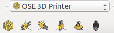

![]() Hint: This changed. To run on FreeCAD 16, 17, 18 - need to take additional steps. See https://github.com/gbroques/ose-3d-printer-workbench#supported-freecad-versions.
Hint: This changed. To run on FreeCAD 16, 17, 18 - need to take additional steps. See https://github.com/gbroques/ose-3d-printer-workbench#supported-freecad-versions.
- To stay up to date with the ose-3d-printer-workbench, within the same directory invoke an 'git pull'
git pull https://github.com/gbroques/ose-3d-printer-workbench- Note: FreeCAD will require a restart in order to take advantage of the updated ose-3d-printer-workbench
- Note: If you are updating and for some reason can't overwrite a directory. Either
- add a write permission for the directory
chmod -R +w ~/.FreeCAD/Mod/
- Or delete the directory first and then repeat the above steps to download it again.
rm -r ~/.FreeCAD/Mod/ose-3d-printer-workbench/
- add a write permission for the directory
Installation Video with Command Line
NOTE: This video is a more technical instruction video for "power users" who are comfortable with command line.
Installation Video for Beginners
NOTE: This video is a friendlier 100% GUI instructional for users not comfortable with command line.
FreeCAD Addons Manager
G also announced the workbench on the FreeCAD forums as part of the process to get it in the FreeCAD Addons repo: https://forum.freecadweb.org/viewtopic.php?f=24&t=45462&p=389451#p389451
This way, the workbench will be available in the FreeCAD Addons Manager for those using FreeCAD 0.17 +.
Demos
1: Frame & Axes
Focuses on creating the Universal Axes in the 3 different orientations (X, Y, and Z) and attaching those to a metal frame for the standard D3D Pro printer configuration.
2: Heated Bed & Extruder
Focuses on adding a heated bed and extruder to 3d printer.
Note: Now you have to hold Ctrl and select one Z axis, and then select the Frame. Then click the button to add the Heated Bed.
3: Frame & 3D Printed Corners
Focuses on adding 3D printed corners (Angle Frame Connector) to frame.
4: Angle Frame Connector (Corner) Macro
Focuses on generating an Angle Frame Connector from the workbench.
Install:
- First install updated 3DP workbench with corners - git clone https://github.com/gbroques/ose-3d-printer-workbench
- Then install the corners macro (see FreeCAD Macros) by copying the macro code into the FreeCAD macros directory, at /.FreeCAD/Macro (on Ubuntu, go to Home folder and hit Ctrl-H to show hidden files to show the .FreeCAD directory).
To run macro:
- Click on Macros at top of FreeCAD, select the macro, and Execute. Macro allows you to produce each of the 8 corners. Note that there are only 3 corner types: tabless (bottom 4 corners), right tab, left tab.
5: Axis Rod Cut List
Focuses on generating a cut-list for the different rods that make up each Universal CNC Axis.
MJ Test:
- If you put in only some of the axes, it gives you only the lengths of those axes.
- Test of what is copied from clipboard:
| Quantity | Description | Length |
|---|---|---|
| 2 | Rods for X Axis | 406.4 mm |
| 4 | Rods for Z Axis | 279.4 mm |
- Or list:
- [2] Rods for X Axis — 16 in
- [4] Rods for Z Axis — 11 in
Usage Notes
Demo Applied Build: 16" bed, 20" frame, double the Z axis support
This design would require an external stepper driver, or RAMPS wired in series on the Z axis at 24 volts so that RAMPS could still handle this larger system.

Roadmap
v0.1.0
I'd like to plan what functionality should be included in v0.1.0 of the workbench, and when to cut the release.
That way we have a stable release, and people don't use the workbench off of the master branch which is considered unstable and could have bugs or features that aren't fully functional.
See also the GitHub issue log:
https://github.com/gbroques/ose-3d-printer-workbench/issues
A milestone on the GitHub repository has been made for the v0.1.0 release:
https://github.com/gbroques/ose-3d-printer-workbench/milestone/1
We can start including issues in this milestone to better plan what functionality is included.
v0.2.0
We can have a similar milestone for v0.2.0, and decide which features or issues should be included in that.
One thing we discussed including at a later date is support for 1" axes.
Workbench for FreeCAD
https://github.com/gbroques/ose-3d-printer-workbench
YouTube Playlist
The first video covers technical installation instructions, and the rest of the videos cover various functionality.
Corner Design
Use Case
We have a specific need for Summer X 2020. We will be building both the standard size version with 8" bed, and also a version with a 12" bed. We think that using the same 8 mm Universal Axis and 1/8"x1.5" angle frames and printed corners, we will be able to build fast (in terms of motion) printers up to about 16" print beds, and slower printers with up to about 24" print beds. Slower because there will be more vibration, so quality printing can be retained by moving slower. Slower motion does not reduce deposition rate as long as large nozzles (1.2 mm) are used - which have typical 25-50 mm/sec speeds. Thus, a larger 24" bed printer can still be built using the same materials as the D3D Pro.
To scale the 1/8"x1.5" to larger size - it is convenient to print out the frame corners at 200% size - without modification. In this case, 1/4"x3" angle can be used, and this is expected to produce up to 4'x4'x8' tall printers using 3D printed corners - printers that are suitable for printing large construction panels using the Supervolcano Nozzle with deposition rate of 20 lb/day. We are also planning to build the 4x4x8 foot printer as such during Summer X 2020 - which will be a simple 200% scale-up of the existing D3D frame parts. The actual axis to be used here will likely be a 1" universal axis.
We have observed an advantage of using hollow shaft instead of 1" solid shaft for the 1" universal axis. We can use schedule 40 3/4" pipe for this purpose, which is close to 1" OD. It is not exactly 1", so we must use custom linear bearings. This is doable using the 3D Printed Linear Bushing. While this bushing is printable in PLA, we will work on printing bushings using Nylon or Acetal Filament using a high temperature print chamber. This is all planned for the first month of Summer X 2020.
Links
- Official 3D Printer Workbench Docs
- 3D Printer Workbench Work Proposal by G Log
- 3D Printer Workbench 2019 - 2019 work by Ruslan Log
- 3D Printed Corners
- 3D printers designed with workbench - D3D v20.04
- FreeCAD External Workbenches - [1]