Aidan Williamson Log: Difference between revisions
No edit summary |
No edit summary |
||
| Line 6: | Line 6: | ||
*[[Aidan_Williamson_Log_2013]] | *[[Aidan_Williamson_Log_2013]] | ||
*[[Aidan_Williamson_Log_2012]] | *[[Aidan_Williamson_Log_2012]] | ||
=August 27. 2014= | |||
Got the machine to run pretty well with some code adjustments. I now drop the main cylinder for a half second before moving the drawer to the eject position. The machine would give high pressure if I didn't do that and the ejection would fail. Haven't tested it with soil in yet. | |||
Repaired a melted tablesaw motor with some JB weld so that I can make the soil sieve stack. | |||
Went looking for more clayey soil. It's mostly marl in the immediate vicinity. I ended up bringing home a wheelbarrow full of some clayey topsoil. Not ideal but better than nothing. I need to go to Little Belize and figure out where their clayey road soil comes from. | |||
The marl test block we made seems to be getting stronger as it cures. It deserves some closer attention. | |||
=August 26, 2014= | |||
Worked on aligning the brick press and tightening any fasteners that may have been loose. I played around with putting shims in to get the drawer to be square with the machine before realizing that it really doesn't matter since the squareness of the bricks depends on the inside of the press chamber and not the drawer. The drawer just provides the top surface. THe only thing that matters with the drawer is that it doesn't deflect when pushed up against so that the top and bottom faces of the block are parallel. | |||
Later in the day we pressed some blocks using the marl beneath our feet. Screened with 1/4" screen and varying amounts of moisture added. No objective measurements. Just a little ball test to get in the right range. We pressed the blocks manually since the auto code still isn't optimized. This is a tedious process that requires turning on and off the power cube and disconnecting hydraulic hoses and using a jumper wire to turn on and off the solenoids. First extend the drawer and drop the main cylinder. When the main cylinder is at its limit turn off the power cube and disconnect the main cylinder hoses. Then turn on the power cube and move the drawer to the obstruct position. Then turn off the powercube, reconnect the main cylinder hoses, turn on the powercube, press the block, drop the main cylinder all the way and move the drawer to its home position. Wait for the block to rise and then push it out. Very tedious process and jumping the wires makes it even more so. We pressed three blocks. THe first one had enough clean surfaces to see how square the block was. It appeared to be square to a 16th of an inch on most sides. The marl doesn't have enough binder in it to work as a good CEB material. It shattered with a light punch. We added more moisture to the next blocks but they were too wet and water seeped around the block as it was ejected. Still it held its shape and we left it to dry. | |||
At some point the 5v regulator stopped putting out 5v and the arduino won't drive the relays anymore. I have to have a usb connection to make it work. | |||
=August 24, 2019= | =August 24, 2019= | ||
Revision as of 18:27, 28 August 2019
My CEB Research DropBox Link
contribs
Old Logs:
- Aidan_Williamson_Log_2015-2017
- Aidan_Williamson_Log_2014
- Aidan_Williamson_Log_2013
- Aidan_Williamson_Log_2012
August 27. 2014
Got the machine to run pretty well with some code adjustments. I now drop the main cylinder for a half second before moving the drawer to the eject position. The machine would give high pressure if I didn't do that and the ejection would fail. Haven't tested it with soil in yet.
Repaired a melted tablesaw motor with some JB weld so that I can make the soil sieve stack.
Went looking for more clayey soil. It's mostly marl in the immediate vicinity. I ended up bringing home a wheelbarrow full of some clayey topsoil. Not ideal but better than nothing. I need to go to Little Belize and figure out where their clayey road soil comes from.
The marl test block we made seems to be getting stronger as it cures. It deserves some closer attention.
August 26, 2014
Worked on aligning the brick press and tightening any fasteners that may have been loose. I played around with putting shims in to get the drawer to be square with the machine before realizing that it really doesn't matter since the squareness of the bricks depends on the inside of the press chamber and not the drawer. The drawer just provides the top surface. THe only thing that matters with the drawer is that it doesn't deflect when pushed up against so that the top and bottom faces of the block are parallel.
Later in the day we pressed some blocks using the marl beneath our feet. Screened with 1/4" screen and varying amounts of moisture added. No objective measurements. Just a little ball test to get in the right range. We pressed the blocks manually since the auto code still isn't optimized. This is a tedious process that requires turning on and off the power cube and disconnecting hydraulic hoses and using a jumper wire to turn on and off the solenoids. First extend the drawer and drop the main cylinder. When the main cylinder is at its limit turn off the power cube and disconnect the main cylinder hoses. Then turn on the power cube and move the drawer to the obstruct position. Then turn off the powercube, reconnect the main cylinder hoses, turn on the powercube, press the block, drop the main cylinder all the way and move the drawer to its home position. Wait for the block to rise and then push it out. Very tedious process and jumping the wires makes it even more so. We pressed three blocks. THe first one had enough clean surfaces to see how square the block was. It appeared to be square to a 16th of an inch on most sides. The marl doesn't have enough binder in it to work as a good CEB material. It shattered with a light punch. We added more moisture to the next blocks but they were too wet and water seeped around the block as it was ejected. Still it held its shape and we left it to dry.
At some point the 5v regulator stopped putting out 5v and the arduino won't drive the relays anymore. I have to have a usb connection to make it work.
August 24, 2019
Reversed logic of pressure switch in code to match reality. It's a NO pressure switch and we are using pullup resistors so we are feeding 5v on pin 13 to one side of the switch. The other side of the switch is GND so when we connect pin 13 to GND we should get a LOW on pin 13. The program was looking for a HIGH instead of a LOW.
We adjusted the pressure switch with an ohmmeter and a jumper cable. Since there is no provision for manual control we had to jumper 12v to a solenoid with a wire to trigger a high pressure for setting the pressure switch. Connect the ohmmeter to both sides of the switch with the leads disconnected and trigger high pressure. While creating high pressure in the system in short bursts, tighten the screw until it no longer reads connectivity and then back the screw off until it just reads connectivity at high pressure. It's a 3mm hex wrench in the pressure switch on the machine.
Added serial communications to the code for debugging. Each state of the cycle will generate text indicating where it is. As does high pressure.
First real issue was that if you wait a long time to switch to press mode from reset mode after the reset homing is complete then it will think that it took a long time to extend the drawer. It then scales this long time (15s or more maybe) to retract to mid-point but even 5 seconds of retraction will take you to the end of the stroke so you will bottom out and the code doesn't look for high pressure. It's just delaying. This is the issue with delays. Eventually I will rewrite the code to do away with delays and while loops but for now I just band-aided that step by replacing the delay with an if and while statement.
This is the original:
                                                 //Step 2 Compression Chamber Closure
if (resetSelected() == false) {
 digitalWrite(SOLENOID_RIGHT, HIGH);
 delay(drawerExtTime*0.75*0.5);           //0.5 is the half-way point of drawer cylinder; 0.75 is the Drawer Multiplier
 digitalWrite(SOLENOID_RIGHT, LOW);       //Can modify the 0.5 to fine tune the drawer closure location
}
This is the version that will move to mid point or until high pressure is read:
//**********************************Step 2 Compression Chamber Obstruction*********************************************
if (resetSelected() == false) {
 Serial.println("Moving Drawer to mid position");
 if(digitalRead(SOLENOID_RIGHT == LOW) ) {
   Serial.println("Current Time:");
   Serial.println(millis(), DEC);
   obstructMoveTime = drawerExtTime*.75*.5 ;     //Duration that the solenoid will be on
   Serial.println("Obstruct Move TIme:");
   Serial.println(obstructMoveTime,DEC);
   drawerEndTime = millis() + obstructMoveTime ; // calculate the time the output should turn off
   Serial.println("drawerEndTime Calculated");
   Serial.println(drawerEndTime,DEC);
 }
}
 Serial.println("here1");
 while (millis() <= drawerEndTime){
    if(checkPressure() == true){
       drawerEndTime = 0;
     }
     digitalWrite(SOLENOID_RIGHT, HIGH);
     Serial.println("here2");
     Serial.println(checkPressure(),DEC);
 }

//delay(drawerExtTime*0.75*0.5);           //0.5 is the half-way point of drawer cylinder; 0.75 is the Drawer Multiplier
digitalWrite(SOLENOID_RIGHT, LOW);       //Can modify the 0.5 to fine tune the drawer closure location
Serial.println("Drawer at mid position");
delay(3000);                             //Delay for slowing operation down for debugging
It's not beautiful but it works for now. In order to do the digitalRead on the solenoid output I had to change the #DEFINE SOLENOID_RIGHT to an int SOLENOID_RIGHT = 0; so that its state can be read.
I also dropped the 20ms pressure switch debounce to 5ms. This appears to help timing overall. I can reduce it even further. 5 was arbitrary. I think 2ms would do just fine. Gotta research that but i don't think contacts bounce for more than a ms.
The drawer extension time measurement is consistently too short. Common values are around 1.7s. This means that the chamber doesn't obstruct fully. This is due in part to the fact that the drawer cylinder isn't starting at its actual home position. High pressure on the main cylinder (second in the series manifold) causes the drawer cylinder to bump forwards a bit more than an inch by the time it goes to extend from fully retracted to fully extended. So I know that this is causing short extension times. There may also be a problem with the way the code is measuring. Changing that debounce value shifted the times longer so that definitely helped.
I need to get the hydraulics in order (press cylinder moving forward due to main cylinder pressure events) but first we need to square the machine up mechanically. It's not square whatsoever. Next step is to loosen all the fasteners, align everything, and retorque the fasteners.
The powercube is running well. The CEB press seems like it will shake itself apart every cycle (as always) and Cecilia went running the first time I ran a cycle. Some hydraulic fittings are leaking. A vise is on my wishlist. Adjustable wrenches will have to do for now. Hopefully i'll get internet access soon to upload multimedia.
The clayey dirt from the mennonite roads expanded a bit more than the marl in a jar test. Still it's more clayey so cutting it with sand might yield good material. Soil testing has been on the backburner because I'm trying to get the press to make a block before Scott leaves on Monday.
August 22 - 23, 2019
Worked on repairing Scott's old broken cement mixer. Frame is bent and keyway in shaft is worn. Rody, Harrol, and I are reinforcing the frame.
Built a workbench to work at near the machine. Started looking at the controller and code. Found a potential issue on line 102. The instruction is to turn off the drawer cylinder instead of the press cylinder. I also noticed (and this is just a stylistic thing) that often there are if else statements when a simple if statement will suffice - there are no arguments in the else portion. I'm going to have to update the code when I add the manual buttons so i'll upload my version when the time is right.
I think there is a need for manual mode because if someone gets their finger or arm stuck in the machine there is no way to move the drawer to help them.
Scouted soil at Scott's first 60acre jungle property. Clayey soil under a decent topsoil layer. Didn't take samples but will do so at a later date.
August 21, 2019
Went to "Little Belize" which is a Mennonite community where they have a lumber yard and a hardware store. The hardware store sells some metal. I bought 40' of 1/8" x 1 1/2" angle, some flattened expanded metal, and some 4x4 screen to make a screen for sieving soil for production. I also picked up some 3/4" x 4" x 84" hardwood from the lumber yard for making the sieves. I brought down 12"x12" soil screens from mcmaster to reduce the price of a soil sieve set. The lumberyard has SO MUCH HARDWOOD!!!! SO CHEAP!!! It's incredible. and they let you pick through the reject lumber for free.I got what I need to make the sieves and a workbench for $30 US. And this is hardwood, not some shitty pine. I'll upload some videos of their sawmill. They planed the wood for the sieves for me. I will start making them soon.
Spent the rest of the day testing power tools. Tablesaw motor is melted at the brush housings. I'll attempt to fix with epoxy. We have several working circular saws. Gabi Harrol and Scott set up some tarps for sun protection while working.
Adjusting to the heat and sun. It's not much different from Missouri in July but my access to water is different and I'm on other peoples' food schedules and I have an issue with a swollen tonsil that is exacerbated by the amount of talking I have to do. Can't complain though since we're in paradise.
While in Little Belize I grabbed a sample of the clayey soil that they use on their roads. It looks more promising than the Marl. Haven't jar tested it yet. I'll need to get a larger sample after I get the sieves going.
August 20, 2019
First week in Belize. Internet access for now is a hotspot on my phone. Not enough data to upload multimedia yet. There is wifi available somewhere in the village but I haven't been introduced to that person yet. We arrived in the afternoon on Saturday. Spent Sunday and Monday getting settled and taking care of the basic necessities of life. Brought all of Scott's tools to the worksite at Harrol's house.
We successfully unloaded and setup the brickpress and power cube. Arranged them in what I think will be a good workflow. The powercube needed adjustment on the choke cable. The people down here who had tested it had been putting gas down the air intake to start it. I adjusted the cable properly so that the choke comes on when it should and the engine starts without any other intervention. Oil was clean and level looked great. I believe Ram changed it. Hydraulic fluid tank was 3/4 full. Air filter was pristine. Won't need the spare parts for a long time.
We hooked up the hydraulics and powered on the brick press with the controller. It didn't seem to be doing what it should be doing. I need to check the setting of the pressure switch to make sure it's not triggering early. The machine seemed to do the RESET procedure properly and repeat every so often. But when I switched to full brick mode it didn't act right. It extended the drawer all the way and then jerked its way back in maybe 1 or 2 second increments. I didn't have my computer handy to check what the machine thought it was doing. I would have to put some serial communications in the code anyway. I don't have a good workspace set up yet so that's the priority right now.
One thing Scott wants to do is make the machine work in a manual mode. There is no way to do that right now besides using a jumper wire to give power to the solenoids inside the controller box. I don't see any manual override on the valves. The 2014 solenoids did have a manual override but I don't see it here. I ordered some momentary switches that should arrive next week. Later on I remembered that I should have gotten NC switches (best practice) but the NO ones I got should work.
I see that there are spare cylinder (tandem spool) valves down here. They're the Eaton VICKERS brand that Surplus Center sells. I have the hirschmann connectors on order. The issue with these is that they are 3.5 AMP coils. It says 30W on the housing but the catalog says 3.5A. I'll test what it really draws. The relays on the controller are rated for 3A. The relays might work at that current since they're not on for very long. We'll see.
Did a jar test on the marl that they build roads with. Marl is a limestone rich soil. It was pretty expansive. Came out to about 5/16" above my scribed line. Just a preliminary test. It may be useable.
August 6, 2019
I'm very interested in the pendulum crusher from the previous log entry. After a correspondence with the owner of Parry Building product, I'm convinced this is a rugged design and the output is claimed to be 20kg/min. If we assume 1800kg/m^3 1 then it would take 90mins to do a cubic meter or 70 mins per cubic yard. This gives 1.75 blocks per minute, roughly. Slow.
August 2, 2019
Clay crushers
- Pendulum Crusher
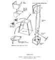
ITW WORKSHOPS PENDULUM CRUSHER
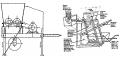
See right side of image
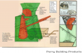
Now manufactured by Parry Building Products.


- Crankshaft crusher:
July 31, 2019
I ordered all the spare parts I think I may need in Belize. The orders are on page 2 of the Tools & Infrastructure spreadsheet at Mader's Machine. I didn't buy a spare pressure relief valve nor any spare hoses. Hopefully the relief valve doesn't kick on, doesn't get hot, and doesn't fail. I did find an alternate pressure switch, New Old Stock from eBay. Same logic and same port size.
Been thinking about the cylinder drift issue recorded at CEB_Controller_v19.01. I read that one way to correct the issue would be to use pilot-operated check valves on the press cylinder. These are $60 from surplus center and prevent a cylinder from moving unless powered.
I do see what Marcin is talking about with the "motor spools" being higher flow than the "cylinder spools". Yuken and Northman both give lower flow rates for tandem(C6) spools vs open center(C3) spools. For Yuken it's about half; for Northman it's about a third less.
I know now that motor spools are also called open center spools which is a use of open center that is distinct from the standard open center vs closed center usage. Yes, they're open center but so are tandem valves which connect P to T in center position but block (to the extent that metal seals on metal) flow from the cylinder to tank. Tandem valves should be used in combination with pilot-operated check valves in situations like loader arms so that cylinders only move when the valve is actuated. The pilot op valves would be a safety redundancy.
So I propose we add pilot-op check valves on the CEB press for a total of $155. This is less than an upgrade to higher-flow D05 valves and subplate in a tandem configuration. My quoted cost includes the additional hoses needed. I believe the check valves could be screwed right in to the subplate outputs. We would need to add Tees to port the pilot pressure to the valves.
July 18, 2019
Sketched up a rough outline of an auger-assisted soil crusher. Trying to solve the problem of relying on gravity to meter the dosage of soil and stabilizer. I think a force like that from an auger would help normalize the dosing. I'm not crazy about it but it could work. Maybe too expensive.
July 17, 2019
Don't have edit access on Soil Mixer Design Doc so I'll record my thoughts here:
- What propels the stabilized soil mixture out of the hammermill?
- Relying on gravity and ratio of areas to dose quantities of soil and earth. This, in my opinion, will be irregular. You would have to be able to change the size of the stabilizer aperture in the field.
- Based on pH for lime. Do a sample every so often
- Based on color for cement?
- The raw soil would need to be crushed and dried before it will fall into the drawer in a repeatable way. This kind of defeats the purpose of a hammermill.
- I could see this propagating the error we have in block size throughout the system. Relying on the soil to fall into a hole the same way each time. Might double the error, right? Double the random uncertainty in block size. Or give a systematic shifts in error during a shift or certain working condition.
- An auger system could meter the input of soil and stabilizer in a more controlled way while still using only one actuator (motor instead of cylinder - though maybe it works out to an extra motor). A variable pulley could be used to set the stabilizer ratio. This is an off-shelf item.
- Example of variable speed pulley system. If we use the same auger size for soil and stabilizer, then gear reduce the stabillizer auger to give 3% to 10% the speed of the soil auger. If you need more than 10% stabilizer then you are using a very low clay content soil and using a ton of cement - rethink the soil blend and if you need to, buy a different pulley.
- Does variable pulley work at low speeds?
- Planetary Geardown? 6 axis CNC Torch Table to produce most components of planetary geardown?
July 16, 2019
Tried to go to the dev meeting to discuss soil mixer per discussion with Marcin last week but nobody was there save an AFK Abe.
Need feedback on workshop tools and infrastructure list at Belize CEB. I'm not including any hardware or materials for the house - just the tools that are required to build it. Just working from what I can imagine would be necessary. Another more experienced set of eyes would be good to glance over what I have listed so far.
Thinking about soil prep: for Marcin's hammermill concept, how do we get dirt at OMC (optimum moisture content) before it goes into the hammermill? One way could be to figure out OMC by volume of dry dirt, volume of water and have laborers fill 5 gallon buckets with dry, screened dirt and add water from another bucket with demarcated OMC line. This unmixed bucket of water and dirt goes in to hammermill. Assume that the dirt has (non-uniformly) absorbed the water AND that the hammermill will actually give a homogeneous mix. I don't see why the hammermill would give a homogenous mix unless you cap the mixing chamber to prevent material escaping before a homogeneous mix is obtained. This would take longer than a press cycle so it would have to mix more than 1 block's worth per round.
July 11, 2019
July 5, 2019
CADded D3D Mill assembly in 2 days
June 20, 2019
June 16, 2019
File:Taper to Straight adapter.fcstd File:Taper to Straight Adapter Wheel Hub.fcstd
Feb 25, 2019
I made a new tube builder when I heard mine wasn't working in FreeCad 0.16 on Ubuntu.
The new file is based on the Sketcher, Draft, and Part workbenches whereas the original file was based on the Sketcher and Part Design workbenches.
File:Alternative Universal Tube Builder.fcstd
Here is a video explaining the new file approach
Feb 23, 2019
Video showing making of a spreadsheet parametrized cad file.
Feb 22, 2019
Made a video about the tube generator and improved the file by adding HoleSpacing parameter to spreadsheet.
Nov 20, 2018
Here is a version uploaded to the OSE Wiki. It should work but may have design flaws. I'm using an O-ring to seal the cylinder in the cap trepan groove. This is questionable.
File:Universal Cylinder Builder ADW.FCStd
I've been working on a cad file for the Open Source Cylinder. Here is a link to the alpha stage of the file. DROPBOX The end-caps are square with a trepan machined for the tube to seat. The caps could potentially be parted so that a welding operation replaces a machining operation for the tube seat. The Rod is welded to the Piston in my version.
Like the universal tube builder, I'm trying to make it parameterized from a spreadsheet. Here is what the parameters look like right now:
Name	Input (Inches)	Output (mm)	Note
Cap Side Length	4	50.8
Cap Thickness	1	25.4
Tube OD	3	38.1
Tube Wall Thickness	0.25	6.35
Piston Thickness	1	25.4
Piston Seal Inner, Height	0.3125	7.9375
Piston Seal Inner, ID	2.125	26.9875
Piston Seal Inner, OD	2.5	31.75
Piston Seal Outer, Height	0.25	6.35
Piston Seal Outer, ID	2.125	26.9875
Piston Seal Outer, OD	2.5	31.75
Stroke	12	304.8
Rod OD	1.5	19.05
Rod Stickout	2.5	63.5
Cap Seal Outer, Height	0.25	6.35
Cap Seal Outer, OD	2	25.4
Cap Seal Outer, ID	1.495	18.9865
Cap Seal Inner, Height	0.25	6.35
Cap Seal Inner, OD	2	25.4
Cap Seal Inner, ID	1.495	18.9865
Need to add a few parameters like tie-rod diameter. I think the model may need to be scrapped. Especially if one looks at the dependency graph lol. I didn't take as intentional an approach to modeling it as I could have.
I believe it is a worthwhile effort, though. A user could generate the CAD for a cylinder of different sizes by simply entering data into a spreadsheet.


Notes
The caps as I have drawn can be easily made on a lathe and mill. How i would make this: Cut the plate to size and machine square. Surface grind for extra credit. Put the four tie rod holes in but make them half inch reams. Using shoulder bolts, attach the plate to a lathe jig or 2 bolts and 2 dowel pins. To make the lathe jig, press fit a piece of 4" or similar crs into a thick plate with the bolt pattern on it and weld. Face the jig on the lathe after welding. The bolt pattern should be put in after the welding operation. Use custom vise jaws and maybe a small bore for picking up the center. For the rod end cap, drill and bore the rod hole then bore internal grooves. Then cut trepan groove. For the base, it's just a trepan. Make those in half a day including making the jig.
As an alternative, I was imagining "slicing" the caps into layers, like 3d printing, and then welding the slices together.
For plastic cylinders, I would start with pvc or abs pipe as the tube. I'd go down that road before I started messing with a metal prototype.
I'll keep thinking about it.
Aidan
Nov 5, 2018
Here is a file that might be helpful for y'all. Open the Universal Tube Builder file and use the spreadsheet to create tubing with all dimensions parametrized. Holes will automatically be set to 4" spacing. I can change that if you want. You can define the standoff for the first hole.