Soil Mixer 2019
![]() Hint: To be prototyped at the Summer of Extreme Design-Build 2020. Canceled due to COVID.
Hint: To be prototyped at the Summer of Extreme Design-Build 2020. Canceled due to COVID.
Soil Mixer Collaborative Concept Design
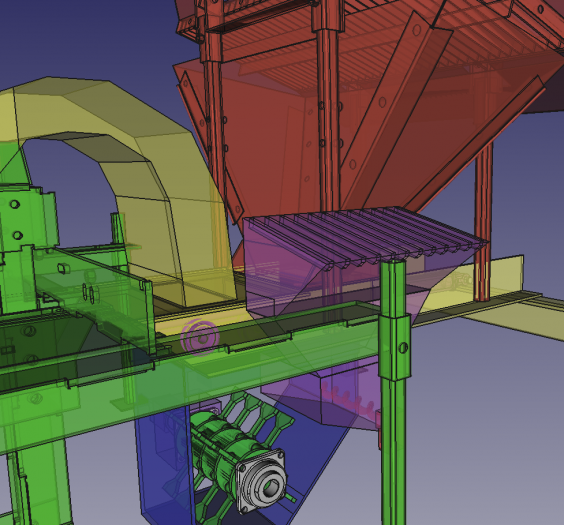
Soil Mixer Hydraulics in FreeCAD

Intro
This is a page that reflects the spirit of collaborative design. There are some subpages:
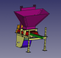
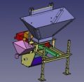
CAD
Visual History
- See also Stock Steel Library
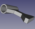
- Design rationale - guide features a 3D printed Herrinbone planetary gear roller on 1" shaft. The outer race of herringbone is curved so that 1" shaft of drawer rides on it while being sidewise constrained. Low cost route for guided motion. Dirt does not get onto bearing groove as top of bearing is under the angle cover.


Part Library
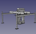
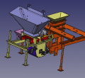
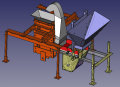
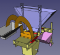
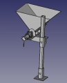
![Hammer mill with CEB Press - FreeCAD on GitLab -[1]](/images/thumb/2/27/Mixerwithpress.png/120px-Mixerwithpress.png)
Hammer mill with CEB Press - FreeCAD on GitLab -[1]
Hammer mill assembly - FreeCAD -File:Hammermillassembly.fcstd
Hammer mill rotor - FreeCAD -File:Hammermillrotor.fcstd
Hammer mill rotor - FreeCAD -File:Hammermillhammer.fcstd
Hammer mill disk - FreeCAD -File:Hammermilldisk.fcstd
Hammer mill chamber - FreeCAD -File:Hammermilchamber.fcstd
Soil loading drawer - FreeCAD -File:Hammermildrawer.fcstd
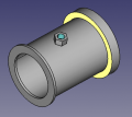
Cylinder - FreeCAD -File:Cylinder.fcstd
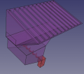
Hopper Assembly - FreeCAD -File:Hopperassy.fcstd
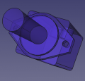
1in Roller Bearing Herringbone - FreeCAD- File:1inRollerBearingHerringbone.fcstd
Press without hopper - FreeCAD- File:Presswithouthopper.fcstd Belize Edition:File:CEB16.09BelizeLite.fcstd
Leg - FreeCAD- File:Leg.fcstd
Auger motor - FreeCAD- File:Augermotor.fcstd
Auger motor - FreeCAD- File:Auger.fcstd
Auger assembly - FreeCAD- File:Augerassy.fcstd
Auger assembly - FreeCAD- File:PTO Hydraulic Motor.fcstd
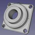
Bearing - FreeCAD -File:2inchbearing.fcstd
Cement doser. - FreeCAD -File:Cementdoser.fcstd

A2+ Version by Aidan
Early Considerations (outdated)
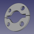
- I'm trying to get the center of mass of the rotor to actually be at the center of the shaft. In order to do this you need high precision like CNC to make the discs so that the 4 bolt circle is concentric with the clearance for the clamshell DOM. I don't have CNC so I changed the build approach to optimize for a lathe, which we have.
- 1" schedule 40 pipe is the weak point on the rotors, in my opinion. Maybe I can find some better tube available locally.
- I have the absolute worst filenames, generally speaking. Sorry. I'll try to school myself on improving this. Putting my name in the file doesn't mean that I claim ownership of it. Please modify ad nauseum.
- I did a different design approach for the drawer guide since we already have some bushings down here from the CEB press. This allowed me to make the chute easier to manage but it means that I had to make the drawer a full 3'. It's not great but it's still only 12" stroke.
- The CEB press v16.09 in Belize is 7" taller than the CEB press in the CAD model
- It would be awesome to do polycarb for part of the chamber body. This could also help reduce the weight of the door. We can get a 0.5"16"x9" (1sqft) piece shipped for $25. This would enable us to look inside the chamber as it works.
GitHub Full CAD Directory(25mb)
Main Assembly
You can also just download the main assembly file and open it up for quick viewing. Now that I removed the fasteners the main file is less than 1mb.
Visual version history:


Open Mixer Press Assembly To View: Download
OutdatedFreeCAD file: File:Hammermillmainassembly.fcstd
Outdated FreeCAD File : GitHub 1.5mb File
Soil Mixer 2019 Main Assembly STEP File (Outdated) STEP File: Github Link
CEB part. FreeCAD - File:Cebonly.fcstd
Soil Mixer part (Outdated). Merge with last file to get full assembly. FreeCAD - File:Mixeronly.fcstd


Modules
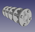
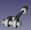
Rotor CAD
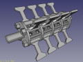
Hammer Mill Rotor - FreeCAD -File:Hammermillrotorlite.fcstd I removed the fasteners so its less than 1mb
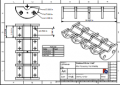
Assembled Clamshell Drawing - PDF -File:Hammermillclamshellweldedhalf.pdf
Hammermill Hammer Drawing - PDF File:Hammermillhammer.pdf
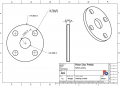
Hammermill Disc Drawing - PDF File:Hammermilldisc.pdf
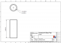
Hammermill Hammer Pipe Drawing-PDFFile:Hammermillhammerpipe.pdf
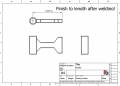
Hammermill Hammer Assembly Drawing -PDF File:Hammermillhammerassembly.pdf


Chamber CAD
Work in progress
Hammer Mill Chamber (Poka-Yoke) - FreeCAD -File:Hammermillchamberassy.fcstd
Hammer Mill Chamber Door - FreeCAD: File:Hammermillchamberdoor.fcstd
Hammer Mill Hopper Stand - FreeCAD: File:Hammermillhopperseatassy.fcstd
Hammer Mill Stabilizer Doser Mount Tube - FreeCAD: File:Hammermilldosermounttube.fcstd


Drawer CAD
36" drawer.
Hammermill Drawer (Poka-Yoke) -FreeCAD - File:Hammermilldrawerassy.fcstd

Chute CAD
Hammermill Chute -FreeCAD - File:Hammermillchuteassy.fcstd

Cement Doser CAD
Hammermill Cement Doser with motor -FreeCAD - Download

CAM
CNC System homebuilt by Midwest Steel in Spanish Lookout. Probably using mach 3 or something. They use AutoDesk Inventor for CAD. Can view STEP files.
Suggested cut considerations:
- Minimum 1/4" + Kerf between parts
- Kerf is usually 1/8" for 11ga and 1/2" plate
- AR400 available in 4x8
DXF / SVG Files
File:SoilMixer2019DXF.zip - sent for quote Aidan Williamson (talk) 18:32, 19 December 2019 (UTC)
Deepnest
Deepnest filles were showing up with "fuzzy" lines on the AutoDesk CAD software at the CNC shop. They opened the deepnest generated dxf file and instead of clean lines there were lines with a kind of boundary region around them. Not sure if this is a deepnest setting or what. The svg generated by deepnest shows up with clean lines in inkscape.


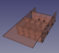
In the following picture I didn't have the view mode set to outline. View->Display Mode->Outline

Design Doc
Design Review
List of Review Questions (please expand)
- Does deflector plate look long enough?
- Can the chamber door be improved?
- Move the chamber up with feet so that the drawer on the mixer is even with the drawer on the ceb press?
- Polycarbonate window- is it safe?
- We might have to use 50mm shaft because we can only get mechanical tubing as "hollow bar" in metric
Calculating Load of on Motor


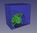
When the hammers swing in, two of them bottom out on the clamshell clamp plates causing the minimum outer diameter to be about 13".
Lets say 25lbs of material is in the mixing chamber. If the retracted hammer hits a 25lb pile of soil at the bottom of the chamber then that pile of soil gives 25lb * 0.542ft = 13.5lb ft of torque on the motor, or 18.4 Nm.
More realistically, the hammers when retracted will hit less than the total amount of soil in the chamber at any instant so the loads will be less. I think the output of my extremely simple calculation, perhaps rounded up to 20 Nm, is a good value to use for the circuit simulation.
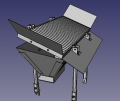
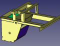
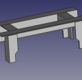
Updated Accessory Rail and Lids
Sorry about the audio.
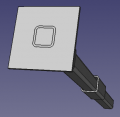
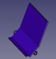
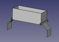
Fixed Chute with Accessory Rail
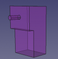
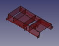
Drawer With Mounted (moving) Chute and Soil Block Lid
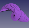
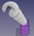
Drawer Motion Study
| 36" Drawer, eject block plate on bottom of drawer | 27" Drawer, eject block plate on top of drawer | |||||
|---|---|---|---|---|---|---|
Build Doc
Integration
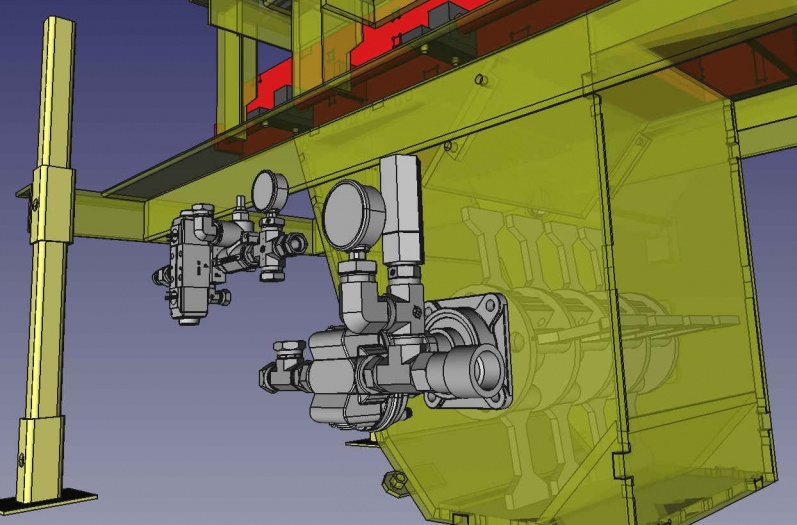
Auger Detail
Modules
 Soil Hopper
- Stabilizer Hopper
- Drawer
- Drawer Guide
- Mixing Chamber
- Rotor
- Motor Mount
- Mister
- Chute
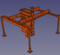
- Legs
- Controller
Build Notes
Belize Machine Tool Availability
- Oxy-acetylene torch
- Super crappy bridgeport - table loose on saddle
- Grinders
- Lathes
- SMAW Welders
- Deming drills
Note: we do not have any CNC capabilities at present. This consideration factors into the design choices I'm making Aidan Williamson (talk) 16:07, 27 November 2019 (UTC)
Update: We do have CNC Plasma Available.Aidan Williamson (talk) 02:13, 3 December 2019 (UTC)
Belize Available Parts
These are things we already have down here so why not use them.
- 1" bronze bushings - bought these as spares for machine before I saw it has nylon bushings
- Auger flighting for 6" pipe. - This is available for $10. It's about a half inch undersized to fit in the pipe
- eaton vickers surplus center type solenoid valve for cylinder
Build Slideshow
Initial Concept
Concept Feedback
Third Round
From Aidan
Auger motor force requirements
From [2]:
0.02HP required for 6" auger at 5.7rpm for 10% stabilization.
- Auger:
- There are some augers in the scrap yard nearby. They were more than 2.5" so I think we're good. OD around 4" IIRC. I'll get some dimensions next time i'm there.
- I don't think we will be able to 3D print one or CNC machine one. We could turn one on a lathe from wood or weld one using Auger technique. I think the best option is to use one that's laying around. I'll see what motors are available at the scrap yard as well.
- I'm getting 45 cu in required for 10% stabilization of a 23lb block (23lb is weight out of the press.) But you would measure it out dry so it's about 21 lb dry material per block or 41.5 cu in of cement per block at 10%.
- Auger Motor:
- We don't have a 120VAC source besides a generator so using a 12v motor would be ideal. We can get a 500W continuous inverter for about $50 so I don't think it's a big deal to go with the cheap gear motor listed.
- OTOH, the controller could easily run a stepper motor but what size would you have to get? Nema42? Then there's the stepper driver requirement...
- We could use a DC gearmotor but those cost around $190 - Power 0.53 HP
Torque 836 in-lbs. The $9 120v gear motor listed in the google doc is rated for about 450VA which I will call about 1/2HP. A 10mm shaft DC gear motor in a comparable price range (including inverter cost for 120v motor) is the 1.4 ft lb DC gear motor 65RPM from ebay. $60. We already have 12v relay boards available for the arduino for up to 10A. The same relay boards would work for the AC gear motor as well.
- Fabrication of Soil Mixer
- In the coming week I will begin to draw fabrication diagrams for the hammermill rotor and we will begin to fabricate it at the workshop in Little Belize. Aidan Williamson (talk) 21:25, 22 November 2019 (UTC)
Second Round
From Aidan
I'm glad to see the design is evolving, that an electronically driven auger will meter the stabilizer, and that a mister will fit into the equation somewhere.
- It looks like one critical area is that the mixing chamber walls need to be a very precise offset from the hammermill teeth so that we get the right velocity of particles going out the chute. This ejection style feed relies on a high velocity output.
- MJ - Yes, 3000 RPM appears to be about 120 mph, not a problem.
- Sorry my comment above was rushed and my point was lost. I'm more concerned about fabricating the mixing drum to the precision we need. Off shelf would be the best bet but i dont know if we can get pipe that large here. Maybe. I'll call around if that's the idea, to use pipe. Aidan Williamson (talk) 17:18, 31 August 2019 (UTC)
- The 375in-lb motor seems a bit weak if we want continuous 3000rpm while loaded. If we're using a standalone power unit can't we get higher flows and move up to a 2 cubic inch motor? What is the limiting factor in increasing system flow? Valves? We're going to be switching the drawer while the motor is engaged so I don't think the full system flow will ever enter the cylinder part - as long as we can do it in parallel. Do we need a valve for the motor? Can't it just always be running? Anyway, I think a higher flow motor would be a good idea if we can do it. 375in-lb is only about 50lbs of force at 8in radius.
- MJ: The motor selected for power input, and here we assume 20 hp max. That should be plenty if our brick pressing rate is 6 bpm. There is no limit to scaling flow - could use a larger motor and larger flow. But I don't think we need more than 20 hp for 6 bpm. This is a tiny hammermill.
- Yes its small and its heavy. The rotor drawn would be about 300lb by itself based on a quick calculation. I'll see what tractor we will be using it with and maybe we can size the motor based on the tractor flow. There are a few guys who have tractors down here that i need to talk to about renting.Aidan Williamson (talk) 17:18, 31 August 2019 (UTC)
- The way the CAD is drawn is not clear on how the rotor is made. Are there multiple clamshell pieces with one side of the clamshell welded to each plate? I'm not sure how we would make it the way it's drawn now. I feel a better way to model it for manufacturing would be to make each part separately and then integrate them in an assembly (like using A2+) so that collaborators get a good idea of how to make it at a glance.
- MJ: Sure. I'll add more build detail, maybe you can do the proper explosions. I tried to put in the build detail but ran into FreeCAD bugs.
- Yes i will do come CAD tonight or tomorrow on it. Still unsure of where to slice the clamshells.Aidan Williamson (talk) 17:18, 31 August 2019 (UTC)
First Round
From Aidan
Hey, here is my feedback on the first concept in question form:
- How do we know that a repeatable amount of soil and stabilizer will fall through the loading drawer aperture? Do we have a way to apply a force other than gravity to give better cycle to cycle repeatability?
- MJ: Depends on soil quality in both cases. Input soil has to have the right moisture content and particle size. Auger AND drawer loader will not work without proper soil quality in the first place. Can you find out from Rob if his Auger works under real life conditions
- Rob is very enthusiastic about his mixer. He says it works great and has offered to work with us to supply a mixer to Belize. Emails here.File:ADW Beddingfield Mixer.pdf Aidan Williamson (talk) 23:21, 13 August 2019 (UTC)
- How can we vary the ratio of soil to stabilizer in the field? Would the users be able to modulate the aperture size?
- MJ: that needs to be designed. Inserts into the cement drawer chamber would be one way to do it.
- What would eject the material up and out of the chute after mixing is complete? How do we know all the material would be thrown out?
- MJ: Hammermill ejects mix when drawer is opened. Tolerance of hammermill hammers to chamber walls determine how well soil is emptied.
- At what point is water incorporated into the mixing process? Is the water added to the soil beforehand? This soil would have a higher moisture content than the final mix would and this would lead to bridging in a hopper. Consider this when analyzing this point.
- MJ: Don't know without seeing how it works in practice.
- The mixing would take longer than a compression cycle. That is my intuition and it may be wrong. Would this one brick mix quantity be sent to an accumulator so that the brick press is not operating at a reduced speed?
- MJ: Conservation of energy says that unless you have another power source, you will get fewer than the rated 6 block per minute that obtain from CEB press only operation. Ideally we have another hydraulic takeoff from a tractor or bobcat that powers the mixer.
- Can we some way do the soil loading without an additional hydraulic actuator (or with a much less expensive cylinder)?
- There is no additional hydraulic actuator. One cylinder runs loading and ejection.
- For Lime Blocks: A retention time is encouraged by texts on the subject, a time between mixing and compression. In what ways could our mixer accommodate this step?
- MJ: Don't know, haven't tried it.
Soil Mixer Genealogy
Industry Standards
BOM
Links
- About hydraulic valves - Hydraulic Valves
- Soil Preparation for CEB
- CEB Microhouse Build in Belize
- Belize CEB
- Stock Steel Library
- Older soil mixer - Soil Mixer and Open Source Soil Mixer
External
- Balancing a rotor - [4]