Universal CNC Axis: Difference between revisions
Jump to navigation
Jump to search
(Organizational Changes + Additions) |
|||
| Line 24: | Line 24: | ||
=1" Universal Axis= | =1" Universal Axis= | ||
See [[1" Universal Axis]] | See [[1" Universal Axis]] | ||
<iframe src="https://www.facebook.com/plugins/post.php?href=https%3A%2F%2Fwww.facebook.com%2Fmarcin.jakubowski.378%2Fposts%2F10211318810383174&width=500" width="500" height="665" style="border:none;overflow:hidden" scrolling="no" frameborder="0" allowTransparency="true"></iframe> | <html><iframe src="https://www.facebook.com/plugins/post.php?href=https%3A%2F%2Fwww.facebook.com%2Fmarcin.jakubowski.378%2Fposts%2F10211318810383174&width=500" width="500" height="665" style="border:none;overflow:hidden" scrolling="no" frameborder="0" allowTransparency="true"></iframe> | ||
</html> | |||
=2" Universal Axis= | =2" Universal Axis= | ||
Revision as of 17:04, 27 February 2018
Basics
- The Universal Axis is a modular and scalable CNC axis which can be used to create cartesian CNC machines. The core of it is belt drive and linear motion rods where carriages are pulled on a rod. The system is scalable to any size and number of axes, including rotary axes. THe system uses a combination of 3D printed parts, metal plates, and belt-driven shafts. Applications include 3D printers, CNC torch tables, heavy duty CNC machines, and many other production machines.
Used For
The Universal Axis - 5/16" Universal Axis
1" Universal Axis
2" Universal Axis
See 2" Universal Axis.
Example of CNC Circuit Mill Configuration, 5/16" Axis
Intro
The following is a 5/16" or 8 mm version of the universal CNC axis described at http://opensourceecology.org/3d-printer-construction-set-workshop/
Larger axes will also be built, up to 2" for heavy duty CNC machining, with plastic parts sandwiched between metal plate as a plastic/metal composite structure. See calculations for beam deflection at Heavy_Duty_CNC_Construction_Set.
Universal Axis - Working Document
- P1 - Visual Linked BOM (VLBOM)
- P2 - extruder stepper motor mounting
Concept
WebGL
Build
Carriage
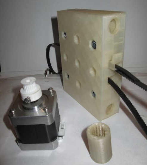
From Michel Dhoore in Belgium in 2016. Early prototype using larger carriage pieces for larger machines.
Frame
Axis
BOM
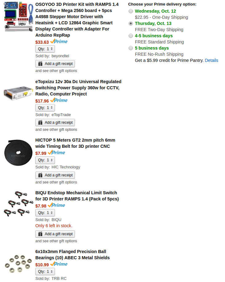
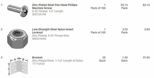
Order
Frame Parts
FreeCAD and STL Files for Printing
Originals from 2016 by Michel Dhoore
This file has the carriage belt tensioners, not shown below.
Universal Axis with Magnet Holes 2017
- File:Universal axis carriage side.fcstd. File:Universal axis carriage side.stl.
- File:Universal axis idler side.fcstd. File:Universal axis idler side.stl
- c
- If using 6x10x3 mm flanged bearings (See BOM), then need a 1 mm spacer: File:Idlerspacer.fcstd. File:Idlerspacer.stl
Fabrication
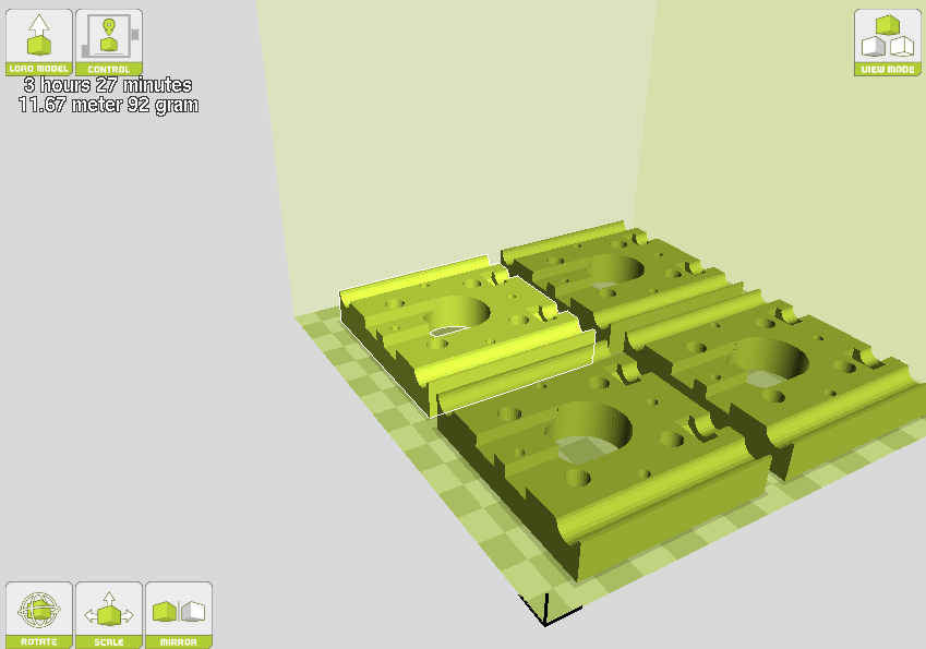
- Print time - 3hr27min for the idler end -
One Axis Attached to Frame
See Also
Useful Links
- 1" Universal Axis
- OSE Germany appears to be doing non-coordinated development on this as well - https://wiki.opensourceecology.de/Erg%C3%A4nzungs-Set_Lineartrieb
- 3D Printer Design Evolution
- 3DP Construction Set workshops - December 2016 - [1]


