Power Panel
Design
- STEAM_Camp_Module_Specifications#Universal_Power_Supply
- January_2020_STEAM_Camp#Day_4_-_Batteries_.2B_Welder_.2B_Power_Panel
CAD


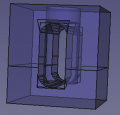
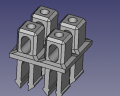
Terminal Block Module. - FreeCAD -File:Terminalmodule.fcstd. STL -File:Terminalmodule.stl
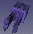
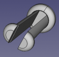
Power Panel Joint. - FreeCAD -File:Joint.fcstd. STL -File:Joint.stl
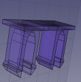
Power Panel assembly. - FreeCAD -File:Ppassy.fcstd. STL -File:Ppassy.stl
3D Printed Terminal Block - FreeCAD -File:Terminalblock.fcstd. STL -File:Terminalblock.stl
Power Panel - FreeCAD -File:Powerpanel.fcstd
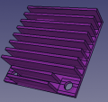
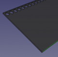
4040 heatsink. File:Heatsink.fcstd
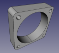
40x10mm fan File:40x10fan.fcstd
Power Module File:Powermodule.fcstd
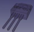
TO220 Transistor File:To220.fcstd
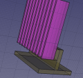
Quickpeg File:Quickpeg.fcstd. STL - File:Quickpeg.stl. Results: with 1.2 mm nozzle, feet break off easily. After breaking one, broke the second taking it off the printbed on D3D Universal. Going square.
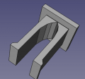
Quickpeg v2 File:Quickpeg2.fcstd. STL - File:Quickpeg2.stl.
Universal Power Panel Generator - FreeCAD File: File:UniversalPowerPanelGenerator.FCStd
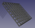
Universal Peg Array Generator -FreeCAD File: File:UniversalPegGenerator.FCStd
Universal Terminal Peg Generator File:UniversalTerminalPegGenerator.FCStd


Production Engineering Data Collection
- Challenging print regarding retraction due to ongoing hops
- Stringing is an issue
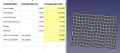
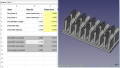
- On D3D Pro - D3D v19.11 6 - File:D3d1911 6.ini. But used 1.2 mm nozzle, 1.1 walls - keeps giving the double outer line upon slicing
- Weird artifact - only at 50-70% flow did it work (1.2 nozzle) - for some reason 100% flow spits out too much material. Never seen a case where flow rate had to be reduced to date. Settings in pertinent part:

BOM
Build
Terminals
Panel
CAD Notes
- 6 ga wire (50A) is 4.1 mm diameter. [1]
Applications
- Open Source Inverter - message to Paul Neelands:
Ideally, the spec would be:
- Division between Arduino Mega + LCD for the brains. We already use this elsewhere - https://wiki.opensourceecology.org/wiki/Universal_Controller. We use that in the 3D Printer and CNC torch table. It has an Arduino Mega underneath. Mega could also use touch LCDs so the interface is super simple.
- Separate power circuit.
- Power circuit is pure sine or as close as possible.
- It is done in modules of 500W or 1kW, so you can choose how much power you want - 1-10kW
- Modular transistor/heatsink assemblies - use one or as many as you want. Since we already use these fans and heat sinks and they work for 40W of power dissipation - can we find a 1kW power transistor that could work with these?
- Clamp-down bus-bar for DC input like the bus bars in breaker boxes so we can attach as many gauge 6 or 4/0 feed cables as needed.
- By default, that would make the above stackable if we have multiple power stages - and a single brain.
- Design the system for 24 or 48V input - and once you do that, we can work out components for other voltages if needed. Ideally, the same system would work from 12-120v or such, and the adaptation to the voltage would happen in software.
- Design with algorithm for NiFe batteries. For the next Seed Eco-Home, our likely candidate will be either 24V 100Ahr NiFe or 48V 100 Ahr NiFe.