Jesse Log
Sunday, Nov.11 2018
Reading up on low voltage buck boost implementations.
Sun, Nov.4 2018
De-soldering capacitors from old circuitry to attempt to make small scale buck converter.
Fri, Oct.26 2018
Reading [this guide http://electronics-diy.com/12v-power-supply.php] For constructing a 12 volt 20 amp solid state power supply. This guide is much more understandable and its also cheaper (most expensive item is transformer). They require input transformers to be safely used with wall current. This is NOT a buck converter, just what appears to be the simplest and cheapest approach for the power supply specifications required.
I've seen people on open source ecology using this cctv power supply that can be had for only $20. This is the current price to beat if we want a cheaper built supply, as these things work very well.
Thu, Oct.18 2018
Reading this guide on buck circuit design.
Mon Oct.15 2018
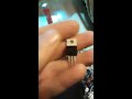
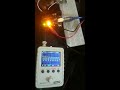
Testing mosfets with arduino pulse and mosfet driver (powered by 9v 1 amp rated transformer rectified to around 12v dc.)
http://img.youtube.com/vi/sglBBMJqtbY/3.jpg
Fri Oct.12 2018
this page is an alright guide for a proof of concept buck converter. Stacking power ATX supplies is still on the back-burner, but lots of components have arrived in the mail allowing me to try some of the boost converter ideas and gain experience with power transistors. Also if we have a low amperage transformer in our circuit to give us 12v to trigger the gate of our transistors, we might be able to bypass a big heavy expensive transformer and just use a buck circuit on the 112v.
The main problem I can see is simplicity vs efficiency. Power electronics design is a complicated topic involving many invisible forces, and to improve the comprehension of our wiki users I feel we should start with simple designs which will cost us efficiency in the short run, but grant us understanding in the long run. This is also an issue of safety- as many of these topic involve tinkering with potentially lethal systems.
Today im using a small rectified one amp twelve volt transformer to drive some mosfets with an arduino pulse and observe the results.
Also found this page on the different types of capacitors one may use or salvage.
Setup a big scary full bridge rectifier capacitor circuit with the 112v from the wall. The capacitor and full bridge rectifier were salvaged from atx power supplies. cap is (560uf 200v electrolytic). This outputs 150 volts DC, and if you make it to this point yourself, always discharge your capacitors or install a bleeder resistor across the terminals, as these things store enough charge to mess you up as well as to blast out a serious spark. Set up small 12V 1 amp power source to drive the IRF540N, which will then drive the IRF250N for the power to our buck circuit.
this site is a useful online circuit simulator that allows easy datasheet and search integration.
Fri Oct.5 2018
Wired an atx power supply to output power without a motherboard. Measured outputs and read up on wiring power transistor outputs in parallel. From what I read its an unstable idea that only kind of works. As an example, say we take the -12ish v output of two power transistors and put them through diodes to prevent back-leakage of voltage into one of the supplies- the next step is to match the two output voltages with resistors so the voltages equally drive a work load. IF we only do these two things, one of the supplies will likely fail after awhile due to component stresses. Im still going to try it to see how long it takes to fail though, as a desperate mans modular power supply, this is getting closer.
The next topic in regards to this is synchronization. If we could use something like an optocoupler to take the pulse driving signal from one of the supplies and use it to drive the pulse of the other power supplies, we could have synchronous pwm going through all supplies which should lessens the wear and tear on supplies if I understand properly...
After studying atx power supplies, its clear that even they employ small transformers for isolation and voltage stepdown. Our earlier plan of just using pulsed width modulation and one pwoer transistor was short sighted- most of the MOSFETS I examined require a driving voltage in the 12v to 16v range. Considering that the whole plan was to use a MOSFET buck converter circuit in order to get a high current 12V source- it seems we will already have to make a few efficiency sacrifices just in order to get a gate driving voltage for our MOSFET.
I found a cool page on building a supply using power transistors in combination with a small transformer. Looks much simpler to implement for would be hobby electronics level people like myself.
Sun Oct.1 2018
While disassembling ATX power supplies for components the idea hit me that these things are ideal pwm buck converters for open projects. They already take our voltage to a safe 12 and 5 volts at a high wattage- we should just look into ways to modularly add these supplies together to increase their wattage. The 12 v would be isolated and the supplies are all safety certified already. As computers become obsolete power supplies are just stacking up in e-waste stations waiting for us to use them in projects. The 12 v out could drive all our motors and can run our power transistors, the five volt supply rails can be used to power our logic circuitry and after that we can add additional voltage ranges and functions such a frequency control.
This gives us a good source of components, as well as a somewhat standardized place to start for would be power supply makers. The voltages are safer to experiment with then un-isolated wall current and would give us a base circuit to modify and experiment with that is already common around the world.
Sat Sep.29, 2018
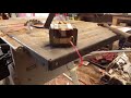
Tried to use irf250 to drive a inductor coil with the arduino pulse. So much heat is produced if the switching time is off, or if the inductor values are incorrect. Makes sense to mount it to a heatsink if im going to keep playing around, as it melted my breadboard a bit...
Thu Sep. 27, 2018
Learned about the Ćuk converter. An efficient class of buck boost circuitry that has less radio loss ( such as I experienced as heavy interference on the twenty third.)
Also found this buck and boost converter physics visualization.
Sun Sep. 23, 2018
Reading up on optocouplers. They are a great way to isolate high power signals from low power signals while still transferring information or signals between the two power levels of the circuit.
- Found and explored this resource
- as well as this one on boost circuit construction
Accidentally burned a mosfet and maybe a diode in an exciting fit of smoke. Was trying a long pulse that was far too long. Accidentally produced a bunch of exciting radio static that I could hear through my amplifier when I left a capacitor attached to part of the breadboard accidentally. Inductance, capacitance, and resistance of these circuits must be understood in relation to pulse frequency. Was using smaller mosfets to drive fan, got the 4422 mosfet driver working well.
Need to get some PNP transistors for the positive half of the signal to go with my NPN's. From what I've read thats the way to go for a boost converter design thats efficient. Might have fried my arduino- it wont take new programs but thank goodness for amazon and cheap arduinos eh? Always use a resistor and perhaps even a diode on you arduino pulse out...
Sat Sep. 22, 2018
Got a bunch of orders in- new mosfet drivers 576-1195-ND some 8 pin dip sockets, a kit full of common resistors (was getting sick of twisting small values together) as well as some pre-soldered buck circuits. Goal now is to drive the bigger mosfet with the new driver, and to use that mosfet to build a boost circuit. Spent the evening messing with the driver on the breadboard.
Tue Sep 18, 2018
charge pump wiki entry. and project related to buck boost circuit which helped me understand whats going on a little better.
Sun Sep 16, 2018
Reading this boost converter power stage calculation guide.
Fri Sep 14, 2018
Took a computer power supply apart for parts. These things kinda make sense when I look at them now, I can see the internal rectifiers, the big 200v line voltage smoothing caps. These are a great source of components which should be in range for this project. Harvested the bridge rectifier, large capacitors on line side of circuit, 12v fan, on/off switch, power plug input, inductor coil 31.3uH (could rewind more wire around core to change value) and a large resistor. Started learning how to use the newly arrived LCR Meter. This makes self winding and salvaging inductors much easier.
Thu Sep 13, 2018
Learning about buck-boost converter design at this page Miles posted. My small audio power supply that I built on Tuesday is still supporting the small amplifier its powering. You get about 1.4 times the voltage with a full bridge wave rectifier hooked up to a proper value capacitor. To clarify, this little transformer salvaged from a microwave has a center tap so 3 outputs. It provides 24 v or 12 v AC out. Currently im rectifying and filtering the 12v volt output and the end result is about 16v DC. A nice multi-winding transformer like this could ideally be routed into several pulse controlled MOSFETS to provide different ranges of voltage for our outputs.
At this point I want to say that its unsafe for us to use 110v wall voltage without some kind of ground isolation. I don't entirely understand this yet, but essentially this will protect us from electrifying a bunch of amateur electronics fellows involved with the wiki. These are some reasons
Started reading this overview of MOSFET implementation. As well as mosfet driver theory.
Here is a nice overview of both.
Tue Sep 11, 2018
Got some IRF540N transistors in! These ones can be driven right from the arduino voltage levels. This guide is an cool resource. Read about ways to measure inductance and found a rough formula. Built a small 12V full bridge rectified power supply using a smaller salvaged transformer from earlier disassembled microwaves. Managed to use salvaged 120 uf 330v electrolytic capacitors salvaged from disposable cameras to smooth it out. The power supply works great and taught me a lot. Next step is to try to build a buck circuit with self wound or salvaged inductors.
Sat Sep 8, 2018
Soldered and tried to drive the MOSFET driver with the arduino pulse. I might not be driving the MOSFET driver with enough voltage, next I'll have to try using two 9 volt batteries. Have been using chains of low value resistors as voltage dividers in combination with DC power transformers to attain test voltages with multi meter on hand as well, though its often pulsed DC and that is not ideal for this test as a new variable. Still waiting for logic level power MOSFETS to come in. Have been playing with arduino output pulse and capacitors to understand the effects on signal with the newly assembled (kit) oscilloscope on hand to test with.
Wed Sep 5, 2018
This page is a great reference for choosing components to make our filter circuit. Have been trying to drive MOSFET with pulse signal from arduino. We want to keep our pulse high frequency so our capacitors can be small and so that our MOSFET is switching efficiently. Will need better code- the long ints are incapable of decimal expression, must use float int.
- Upgraded PWM code to allow variable resistor PWM control as well as increasing the timing circuits speed to reduce component size/cost.
- Added IRFP250N to possible parts section of Adjustable_Power_Supply_v18.08
- Learned there are different kinds of MOSFET's- only some (logic level MOSFET) of their gate thresholds can be directly driven from arduino voltage. Other ones require use of MOSFET drivers- which Ive been trying to get to work but having some trouble with. Put in an order for some Logic level MOSFETS

- Uploaded video showing the pulsed width modulation
http://img.youtube.com/vi/oCyFZBC3bY8/3.jpg
Fri Aug 31, 2018
Deepened understanding of PWM operation via arduino code and summarized below. The arduino has a base frequency which can be modified to control our PWM frequency. So for example we could change the frequency of the square pulse to 60 Hz- then we could PWM the 60hz frequency to %50 duty cycle so its on half the time effectively cutting the pulse of each individual 60hz pulse to half its length- which equates to cutting its voltage in half (with help from a proper value capacitor?)
The arduinos base frequency is 31250 Hz for pins 3, 9, 10, and 11. The base frequency for pin 5 and 6 is 62500 Hz. Using the above links referenced functions, its possible only to modify the frequency with certain dividers applied against the base frequency.
The arduino also employs three timers, which are shared across many device functions and pins.
- Pins 5 and 6 are paired on timer0
- Pins 9 and 10 are paired on timer1
- Pins 3 and 11 are paired on timer2
The divisors available on pins 5, 6, 9 and 10 are: 1, 8, 64, 256, and 1024. The divisors available on pins 3 and 11 are: 1, 8, 32, 64, 128, 256, and 1024.
This leads me to our first potential problem- 62500 HZ divided by 1024 is 61.035 Hz. I wonder if thats close enough to sixty to get by, or if that would cause devastating drift that would effect some devices? (Turns out this in no problem at all, we can use a high clock speed and just use a simple delay command to determine our on off pulse time.)
Started pulsing an LED through various frequencies and duty cycles with code from this page.
This is an enlightening read on the value of not using delay to time things.
The code example I found here will perhaps suit our purpose with some modification...
Updated code for PWM.
Thu Aug 30, 2018
Read about arduino PWM implementations. For pulsed width modulation there are at least two different methods I've found so far for generating a square pulse on one or multiple arduino out pins. One of the methods also allows you to control the frequency of the duty cycle being employed for PWM. This would let us get some useful signal modulation options for our power supply.
Wed Aug 29, 2018
Arduino PWM tutorial will be used to generate the beginnings of our pulse width modulation code on my end as an example. Ill try to use that pulse to modulate some smoothed DC voltages with the mosfet and mosfet driver I received yesterday. We need to look into having a 5 v source for the arduino as well as a 12 v signal to drive our mosfet driver- so we may need to explore winding our own torroidal transformers (or finding a cheap source of them) to get some multi tap action going once we modulate the power and put it though said coil. Until we get that far ill be powering the low voltage parts of our circuit via battery to simplify testing and design.
Tues Aug 28, 2018
Received parts! (Power MOSFET and MOSFET driver) Designed a basic circuit after studying their output terminals in datasheets. Will run it all by Miles first to see what he thinks, my plan is to use rectified and smoothed 120V as the voltage source for the Power MOSFET. At first I figure we can use batteries to power the 12V (4.5-16V supply) MOSFET driver as well as the arduino so as to simplify design. With this setup I plan to test the mentioned components to see if we can get our arduino pulse to modulate the 120V DC. If that goes well we can look forward to designing power supplies for the battery powered components and then using the modulated 120 V to further our boost/buck circuit.
Sat Aug 25, 2018
After messing with rewinding transformers for over two weeks I have learned a lot about making transformer spools, safely operating high power equipment for tests and reverse powering a microwave transformer. Of all the things I've tried, powering a core through the secondary coil seemed the most viable to get our power, and it was still extremely prone to inefficiency in heat and vibration as well as stray magnetic fields. Not that transformers do not have their place- just that they are a lot of trouble for an inefficient end result. I noticed Miles is making progress rectifying 112 v for the arduino, and I now agree switched power supply right from 112 V seems to be the way to go. Still got lots to learn but my next goal is to try to drive a IREP250 with a TC1411 and arduino. Need to look into getting some signal graphing equipment like an oscilloscope.
This is a good read about switched mode power supplies.
Fri Aug 24, 2018
Added possible parts to power supply design
Thu Aug 23, 2018
- Assembled and tested full bridge rectifier using solder and 4 15SQ045 diodes. Tested it with secondary driven unmodified transformer. (.272 V 6.5 A)
- Built a wire spool around my 3D printed form using cardboard and masking tape. Wound some 22g enameled mag wire to 70 turns (3 layers insulated with masking tape)
- Found two microwaves (free)! Salvaged all components. One is a massive one from the 70's or 60's on which the transformer was huge and all the components were dated and larger.
- Will attempt to use reverse (secondary powered) microwave transformers in parallel to increase power output. Will also test newly re-wound transformer.
- Ordered one of these things- they are affordable CCTV camera power supplies (like $18 USD) that might be studied for design or used with buck-boost circuits directly to achieve a quick range of power which could then be controlled and used by the arduino. Until we have our own circuit made this would let us begin to test the rest of our system.
Wen Aug 22, 2018
- Re-wound microwave transformer for second time and tested at 1 amp and .5 volts. Will re wind today with thinner wire to fit more turns. Last results obtained with 55 turns of 10g enamel wire. Insulative rubber strips can be salvaged from bicycle inner tubes to be used as layers of transformer insulation between the stacked coils to preven arc-over, which did happen and is usually caused by broken wire enamel caused by sharp transformer edges. Need to do a heat test and burn some of that insulator to make sure its not a crazy fire hazard like it might be.
- Designed and began 3D printing a wire spool shaped like the transformer metal to ease coil winding.
- Talked with miles about transformer design. Will try running voltage through an unmodified microwave secondary coil to see how it effects the heating of the core and the power output. (20:1 microwave winding ratio)
- Measured 0.272 Volts and 6.5 Amps when I ran the transformer without a load with wall current flowing into an unmodified microwave transformers secondary coil! Awesome idea Miles! The transformer did not initially appear to be adversely effected when wired in reverse. Ill see if I can do some metal melting with this setup to see how it responds to a high load. Follow up guides will be on the way but as we are now up to like 6.5-7 amps everyone needs to be very careful and always follow the one hand rule!
Wen Aug 15, 2018
- Began compiling transformer disassembly/rewinding videos.
- Some notes were generated in a conversation with Miles and Marcin:
"I think we should try both and record the results! I've got some diodes in now so I can rectify the wall power then break open a few PC power supplies for hopefully ballpark capacitor values. My adventures in rewinding transformers have led me to believe that we should likely wind our own rather than subject people to the power tool experience thresholds needed to disassemble a core gently enough to preserve primary windings. Finally yeah, I think if we can find a way around a transformer we should, I just respect the things as a common component worth getting to know.
Winding our own transformers would give us the ability to wind multi tap transformers for a large range of voltages which could be rectified more efficiently if the power loss from the buck boost/ arduino controlled power transistors is too great.
So I wonder, if we rectify the 120V AC then smooth it out with a nice big capacitor, I think then we could just use something simple and easy like a voltage divider to give the arduino the power it needs to start regulating the now smooth DC into duty cycles through power transistors... I could be wrong on that and the buck boost is the stable way to go, but at this point we will get to try some things and see what works unless anyone has some more definite direction for this after the rectification and capacitor smoothing parts.
Finally, have any of you had any luck modelling existing components not in the qucs library into the program? I can just try and build a rectified smoothed transformer-less power supply and measure it and see what happens in real life but simulations are more efficient. "
- Compiled and published transformer salvage video.
http://img.youtube.com/vi/vSWjAaGHV_4/default.jpg
Tue Aug 14, 2018
Finally got a solid hit looking for used kijiji microwaves. Arranged a meeting nearby and will transport it home for the great price of $15. Another one lined up for Friday. Once I've got the used microwave I'll get to work on making the safe microwave transformer salvage guide.
- Went to get the microwave! Brand is Emerson, specs on back claim power of 1.4KW single phase grounded with max power output at 1000W max.
- Added transformer steel to Electronics List
- Attended my first video meeting!
- Disassembled microwave and recorded process of disassembly and salvage of transformer. Safely disassembled core and found ways to remove the primary coil with minimal damage. It was really difficult work though, it really might be easier to make our own transformers once we could find an affordable source of transformer steel.
- My next task will be compiling the video I took from various camera sources into a how to guide with kdenlive.
Rewound transformer and re attached primary. Temporarily reassembled core to test for voltage (multi-meter read 0.075V, might really be 75V cant be sure will get new meter) and amperage (1.4A), touched the wire together on my re-wound secondary coil for an intense spark! It would be interesting to see what a buck boost converter could do with the stepped down power.
Maybe we could consider using multiple points in our power supply which were rectified then put into a buck boost circuit (one at wall voltage, one at stepped down voltage, perhaps one at a higher voltage, so as not to strain their range/loss?). Lots of video to compile now though!
Mon Aug 13, 2018
Read the safety considerations in power supply design pdf file.
Sat Aug 11, 2018
Practiced using Quite universal circuit simulator.
Fri Aug 10, 2018
Created Microwave Transformer page on wiki. Linked newly created page to the possible parts section of the Research Development page for the Universal Power Supply.
Some of the parts salvaged from the microwaves might have use in the Universal Power Supply project. There are some high voltage relays, micro switches, and some nice fans that run off 120v AC. This is just to name some of the parts. While safety should be considered if you are going to harvest the microwave capacitor as well as the magnetron- as long as you discharge the capacitor and bag up the magnetrons you salvage you should be fairly safe as long as you follow safe electronics practices. The magnatrons contain a dust thats bad for lungs so they should be sealed away in airtight bags.
Also learned about QUCS (Quite Universal Circuit Simulator). Downloaded and installed a copy and found a Tutorial..
Thu Aug 9, 2018
Studied:
       * Current tasks
       * Crash course on Power Electronics
       * Electricity
       * Electronics List
       * UPS Initial Design
Contacted two more Kijiji users about cheap used microwaves in range.
Wed Aug 8, 2018
Sourced a few cheap ($10) microwaves on kijiji in the area and contacted sellers.
Tue Aug 7, 2018
Finished modelling then uploaded free-cad model of microwave oven transformer core. Ordered some KBPC5010 high current bridge rectifiers.
- https://wiki.opensourceecology.org/wiki/File:Transformercore.fcstd
- https://pdf1.alldatasheet.com/datasheet-pdf/view/34010/WTE/KBPC5010.html
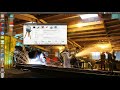
On a side note, I successfully salvaged three microwave fans and mounted them to a wooden frame, then connected them to a wall main in parallel. They all run on 120V AC and are a convenient salvage for cooling future projects (and work-spaces!)
Mon Aug 6, 2018
Recorded dimensions for one of the disassembled microwave oven transformer cores. Also recorded transformer core slice thickness at .025" or .635mm and began modelling the transformer in free-cad. In the future I should make a short guide on salvaging parts from microwave ovens and what can be found as well as the best ways to get at the goods. Should also look into places from which to order the core slices to replicate this design or one similar to it in the future. The slices, if made from scratch, should be painted with an insulator to reduce magnetic eddy currents which contribute to heat buildup. Cold roll steel seems to be the way to go. This article states a silicon content might help as well if we ever end up pouring our own steel.
Sat Aug 4, 2018
Disassembled one microwave oven transformer. Learned how to liberate the primary and secondary coils- but need to be more gentle next time, I damaged the enamel on the winding for the primary so I'll have to try again with another core. Got an unmodified core hooked up to power and producing arcs in order to have a hands on understanding of a high power transformer in operation. We should mount it on a massive heat sink if we end up using this component. I plan to model a microwave core in free-cad soon for reference, will have to engineer a hinged transformer core or maybe just screw holes for easy core winding access if replacement winding need ever be addressed. Ordered some different gauges of enameled copper magnet wire.
Fri Aug 3, 2018
Studied the Universal Power Supply. Noticed the possible use for microwave oven transformers, in all of their high power glory. Decided I'm going to try to rewind a microwave oven transformer core secondary winding to provide 30v at around 2 amps to the buck converter circuit, which I ordered ten of off amazon for something awesome like $2.40 a piece.
Thu Aug 2, 2018
Learned the basics behind how to dimension drawings in free-cad. Took half an hour to download and explore dimension drawing workbench. Still need to learn how to change the Title and info in the bottom right table. This is what I have so far. Practice dimensions
Sent an email to info@opensourceecology.org to notify them of completed steps.
Wed Aug 1, 2018
Learned how to use Vokoscreen to record myself through the webcam on my laptop which was running the OSE live-USB. Recorded the video interview questions and uploaded them to youtube.
http://img.youtube.com/vi/9y8gRox_JXI/3.jpg
This took about an hour and a half to get to work as I had to calibrate it to proper settings to get it to record the sound in sync with the video.
In the end I used Window style recording and clicked on the webcam window to record just my image while reading the questions. I left the frame rate at 25, changed the videocodec to mpeg4, avi and the audio format I left at libmp3lame.
Sent off an email to ops at ops@opensourceecology.org to let them know I've completed the steps in the list.
- Update: Linked to corner_cube_test_video and learned how to upload my freecad file to the wiki.
Download corner_cube.fcstd
http://img.youtube.com/vi/zroXi9xBAUY/3.jpg Link to Corner cube test video
Time frames:
- Installing Linux: 20 minutes
- Learning Free-cad: 3 hours of trying to get faster and more comfortable.
- Documenting my work: 2 hours learning to organise on the wiki.
The hardest part was learning to use Free-cad. Its a tricky program with tons of tools and features.
Ill give myself a score of 95%. I'm missing some formatting techniques to make everything here appear clean and concise.
Tue Jul 31, 2018
Created live-usb and installed OSE Ubuntu OS to my desktop computer. Used the live CD on my laptop to record the desktop video due to microphone requirements. I'm having a hard time getting the sound to work with clarity on my laptop microphone for the video interview so ill give it a try tomorrow or start looking for old external microphones around the city. Recorded developer test video. Learned to edit video down to appropriate size and uploaded to youtube. OSE_DEV_TEST
Freecad is a lot to learn but now that I can use it a bit more reliably, its not crashing anymore and I am learning ways to speed up my workflow. One of the most useful tricks was the (ctrl) selection of files to mass rotate a bunch of copies. This saved a lot of time and will be a useful technique in the future. Hot-keys and always save!