Universal Power Supply/Research Development
| Universal Power Supply | ||
|---|---|---|
| Home | Research & Development | Bill of Materials | Manufacturing Instructions | User's Manual | User Reviews | 
| |
The universal power supply contains the power electronics and power supplies for:
- Welders
- Plasma Cutters
- Battery Chargers
- Induction Furnaces
- CO2 Laser Cutters
- Stepper Motors
- Charge Controllers

Applications
- Powering welders, plasma cutters, battery chargers, induction furnaces, CO2 laser cutters, reprap
- Inverters for household power from batteries
- Voltage regulation/conditioning to get grid-quality power from variable power sources such as windmills, steam engines (especially solar powered)
- Battery charging from windmills, steam engines
(the other mechanical components of the above devices are covered as separate tools of the GVCS)
Physical Dimensions
As an example, the Zapp Star 1000 Nickel-Iron Battery is listed as 15" x 6" x 20". Ten of these for a 12 volt battery with 1000Ah would require 10.4 cubic feet with an approximate weight of 1400 pounds (using similar BeUtilityFree specs). This is not man-portable. Scaling down to 12 volts at 100Ah reduces the dimensions to 1.5 cubic feet and 150 pounds. Build ten of these and you can wire them in parallel to increase work time or in series to increase voltage (which may be advantageous in charging). Assume roughly 1.5 cubic feet 150 pound 12 volt 100Ah battery cube.
What are the dimensions of hydraulic power cube? Use the same cube frame? -The power cube seems to be 2' x 2' x 2' so it's 8 cubic feet. I'm gonna go ahead and assume the battery on the zappworks homepage isn't the one referenced in the spec sheet. This one looks more like the dimensions listed. The dimensions of the power cube are probably exterior, so the interior dimensions are probably less than 24". You could fit 4 of the Zapp Star batteries for sure. However, adapting the technology to a more GVCS-appropriate set of dimensions would be beneficial. For example, a power cube's volume could be divided up neatly into 5 sections of 24" x 24" x 4.5" which works out to exactly 1.5 cubic feet per section. So you'd use 7.5 cubic feet of the 8 available. Based on the weight you used previously, filling up 7.5 cubic feet with nickle-iron batteries would weigh almost exactly 1000 pounds. The LifeTrack could move three of them at a time. More importantly, 2' x 2' x 4.5" batteries would neatly stack right next to a power cube. One could be bolted on by itself or five could be jammed into a pseudo power cube frame. You'd just add one more battery whenever you wanted another 100Ah. Assuming 10 cells per battery, that would make them each around 2.4" x 4.5" x 24". I don't know if that's a practical set of dimensions for each cell.
Other specifications
- Scalability via modular add-on
- Quick disconnect components wherever possible
- Logic circuits millable with basic CNC Circuit Mill
- Insulators printable with 3D Printer or Ceramic 3D Printer
- Ability to operate with any voltage from a few volts to 1kV
- Ability to generate any frequency
- Open Source Enclosure - enclosure design that allows maximum scalability and flexibility
- Design for flexible fabrication via Open Source Fab Lab, initially using off-shelf components
In practice, the above will be implemented by refining one functionality after another, and adding modules that will allow for different functions and scales.
We're interested in a universal, modular power conversion device for electricity. I am talking about different modules that can be plugged together for something like a Lego Set of power electronics. Each module would in itself be modular, so it can consist of a number of units connected for scaling current or voltage.
Modules
- 50/60 hz electricity at common voltages such as 110 or 230 or 440
- DC current for plasma cutters or welders
- Battery charge-controller current
- High frequency power for induction furnaces
- Regulation of variable voltage (say 60-230 v AC) to charge batteries
- DC-DC conversion.
- Synchronous inverter so that multiple units can be stacked for applications that require higher current
That just about covers all power devices for advanced civilization, more or less.
Design Path
The general scheme would be to: (1) rectify a typically oscillating input from some power generating device, if it's not DC already, (2) chop it up, (3) scale it, (4) form it, (5) and finally, spit it out as DC or AC.
We want to create a universal switched mode power supply kit, with some power conditioning and regulation.
Please propose a basic starting circuit with the following specs: (1) Takes any AC input (from an ac generator) to either battery storage or an inverter/converter. (2) Specify parts for a system that can runs from 100W to about 20kW for starters. Is this feasible, or is the problem statement ill-defined?
After the above, we'd have to go to 3-phase converters, since many appliances of interest (such as induction furnaces) run off 3-phase.
Power Supply R&D
Initial Design
The following design may not be safe or functional. Use at your own risk.
[[1]]
Qucs-s Simulations
800W Power Supply (work in progress)
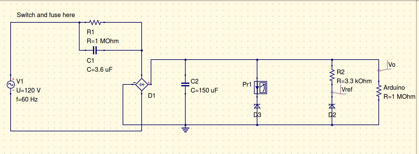
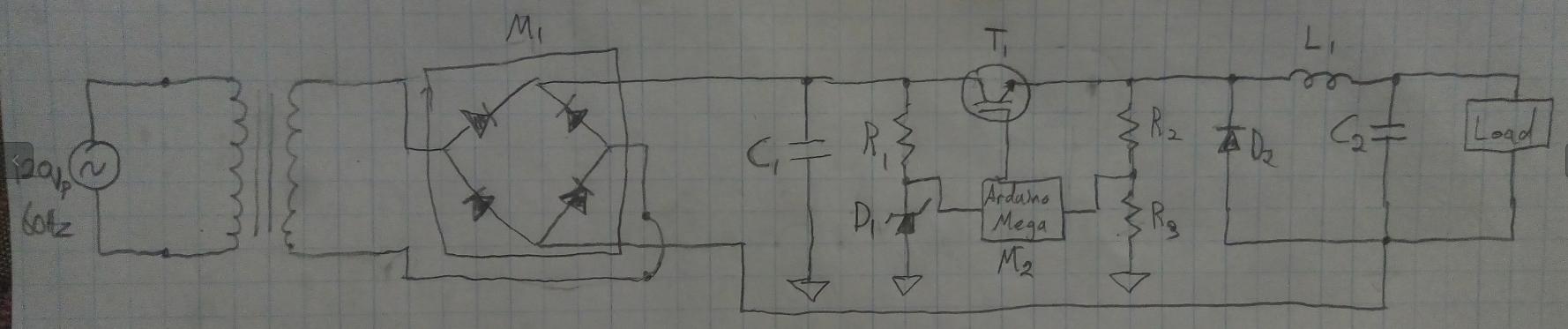
Non-Isolated Arduino Power Supply (this is designed to supply up to 100mA)
Research
Power requirements for Arduino Mega (usually <70 mA, 200 mA max) and RepRap Discount Smart Controller (40-100 mA?). 300 mA max to power control and display circuits.
Drawing Power from Grid without Transformer for *Low Power* Applications
Precise voltage measurement with the Arduino
Safety Considerations in Power Supply Design
Current Sharing in Parallel Diodes
Low-Pass Filter a PWM Signal into an Analog Voltage
Using PWM Output as a Digital-to-Analog Converter ] Maybe possible to reuse transformer from microwave (~800W).
High Efficiency 400W AC/DC Power Supply Reference Design
Understanding Buck-Boost Power Stages
Fully Digital Power Supply Modules for Telecommunications
Possible Parts
4.030 Schottky Diode, 45V, 15A
Salvaged Microwave Transformer
C = I*t/ΔV for filter capacitor [2], where:
C = capacitance [F]
I = current [A]
t = period of oscillation [s]
ΔV = peak-to-peak ripple voltage [V]
Inverter Research and Development
OffShelf Options
Few high power stackable inverters without bells and whistles exist. Of those, modified sine wave appears to be the majority.
http://www.chinesegrid.com/Stackable-Power-Inverter/sun-2500w-stackable_SUN-2000W-Stackable.html
Input 24V and output 230V was identified.
http://www.chinesegrid.com/Stackable-Power-Inverter/sun-2500w-stackable_SUN-2000W-Stackable.html
Price between 150 and 250 USD each. 80% of rated power should not be exceeded in general.
Based on youtube videos people seem to be doing ok with other sun inverters.
Alibaba also says this company is verified and has a paid membership for doing serious business with customers.
Based on some modified sine wave inverters being sold complementary to welders, deduction led to modified sine wave inverter-welder compatibility.
- Inverter Function is to input direct current (DC) and output alternating current (AC).
- Direct Current is the flow of electric charge in one direction.
- Alternating Current is the flow of electric charge in reversing directions.
Theory
- Electromagnetic Induction allows the transformer to take an (AC) input voltage and current and give a higher or lower output (AC) voltage based on the ratio of wire turns wound between transformer coils. (inductors)
- Commutation periodically reverses the direction of charge flow of direct current as to produce alternating current. Digital signals for solid-state commutation can be produced with an oscillator circuit.
- Electromechanical Inverter contains electrically switched moving components that facilitate commutation.
- Solid State Inverter contains non-moving transistors that facilitate commutation.
- Stackable Inverters can be connected together to the same DC power source in order to supply greater AC output power.
- Types of Alternating Current include square wave, modified sine wave, triangular wave, true sine wave, and more.
- Transformer or Transformerless represents the design choice of having or avoiding a transformer within the inverter.
- Galvanic Isolation refers to the separation of circuit sections such that direct current cannot pass between them but energy can be still be transferred through other means such as induction. An isolation transformer can be used to achieve galvanic isolation.
- Switching Solid-State Transistor: Insulated Gate Bipolar Transistor (IGBT) or Metal Oxide Semiconductor Field Effect Transistor (MOSFET) - represents the design choice between MOSFETs or IGBTs as part of the driving circuitry.
- Master and Slave refer to the situation where multiple inverters are stacked in parallel. In order for the output AC to have a synchronized waveform, the phase generation must be performed by a single source and the phase output connected to all inverters in the stack. The phase generating inverter is called the master inverter, and the phase receiving inverters are called slave inverters. The connecting wires between the inverters for phase sharing are called phase cables.
Systematic Breakdown of the True Sine Wave Inverter
Specifications
- Input Voltage = 12 VDC
- Output Voltage = 120 VAC
- Output Frequency = 60 Hz
- Output Waveform = true sine wave
- Stackable = true
- Transformerless =
Overview
- Case - contains and protects the electronics.
- Voltage Regulator - changes the input DC voltage to 6VDC for powering certain components of the inverter circuitry.
- Boost Converter - increases the input DC voltage to 170VDC for powering the H-bridge.
- Oscillator - generates the reference sine wave.
- Reference-to-PWM Circuit - receives the reference waveform and outputs corresponding trilevel PWM signals.
- PWM-controlled H-Bridge - receives trilevel PWM signals and correspondingly allows current to flow through its load in alternating directions.
- Filter - reduces the harmonic distortion of the output AC waveform.
Case
- Basic Shape - is a hollow rectangular prism.
- Positive Input Opening - is for the input positive DC voltage.
- Negative Input Opening - is for the input negative DC voltage.
- Ground Opening - is for the inverter's connection to earth.
- AC Opening - is for the type B AC outlet. The case has two AC openings.
- Master/Slave Opening - is for the switch that determines whether the inverter is master or slave within a stacked set of inverters.
- Power Opening - is for the switch that connects or disconnects the inverter from the DC inputs.
Voltage Regulator
Boost Converter
Oscillator
- Bubba Oscillator produces a reference sine wave and consists of 4 operational amplifiers and 4 RC filters.
- Op-Amp 1 is an inverting op-amp with a gain of just over 4.
- Op-Amps 2 to 4 are non-inverting op-amps with unity gain.
- RC Filters 1 to 4 cause a phase shift of 45 degrees each for a total of 180 degrees phase shift. RC Filters 1 to 4 also filter and control the frequency of the output sine wave.
Reference-to-PWM Circuit
PWM-controlled H-Bridge
Filter
People
- Heath Matlock - interest in Universal Power Source (including plasma cutter and induction furnace) and free fabrication - part of Austin party - http://freefab.org/
See also
Forums and Groups
- Power Management forum - [3]
Links
- Transformerless Power Supplies - [4]
- 100kW open source inverter for AC induction motor - [5]
- Paper on Low-Power Square Wave Inverter Including Circuit Diagram and Specific Explanations
- Paper on Medium Power True Sine Wave Inverter Including Circuit Diagram and Bill of Materials
- IGBT Versus MOSFET
- Thesis Paper Including Inverter Information
- Design Reference: OpAmps For Everyone
- design tutorial cached