OSE Shop 2011
Main > Housing and construction
Planning
Introduction
This year, we are putting our construction tools (CEB Press, Tractor, Soil Pulverizer, and Power Cube) through the most rigorous field test to date: the construction of 10 living units and a 3,000 square foot fabrication facility here at Factor E Farm. We have already achieved the highest brick pressing rates of any open source model (slide: 16 bricks/minute, 5,000 bricks/day), and now we are aiming to complete the package by achieving five dollar per square foot construction costs while remaining within industry standard construction schedules. Our goal is to improve dramatically the efficiency of natural building, far surpassing the benchmarks of earthbag, cordwood, strawbale, cob, rammed earth, adobe, earthship, and papercrete techniques while keeping the ecological footprint to bare minimums. We will publish a full energy accounting report, including embodied energy estimates for materials and the "joules per day" of both biological and electromechanical systems.
So far as we know, this will be a global first: the highest embodied energy efficiencies and the highest construction efficiencies at the lowest cost and with the least environmental impact. Our aim with This Last Mile is to lower the barriers to creating sustainable human settlements by providing access to powerful, low-cost, open source tools that anyone can use to build and transform their environment.
2011 Workshop Building Implementation
Initial Build
We had a group of students come in -
This actually did not work - a few days later, there was rain, and the columns, left unprotected - got destroyed. Unstabilized block and water do not mix - so we went to Try 2 as winter approached. We ended up framing, putting on the roof first, and then laying brick walls instead of using columns like we planned initially.
Building Project Updates
Project Manager David's latest progress report on the project.
Shop Instructions At This Stage
Instruction pages for each step of the project are being prepared and will be posted periodically as time and availability allow.
Planning
How to make a water level: http://www.youtube.com/watch?v=nAcT_1T25LM
Also see Factor_e_Farm_Infrastructure_Buildout_2011
STAGING AREA CONSIDERATIONS
This shop project has a modular design. This way, the need to fabricate parts doesn't slow or interrupt the putting-it-all-together part of construction. However, this requires storing and protecting building supplies for fabrication before they are used; a work area for preparing the modules needs to be considered; and pre-fabricated parts will also need to be stored and protected between the time they are fabricated and the time they are needed. Where to keep them - especially the large ones like roof frames and roof stringers - deserves some consideration.
- Building Supplies
- Location
- Close enough to the pre-building tools and equipment that parts don't have to be carried too far.
- Close enough to the module storage site that completed assemblies don't have to be carried too far.
- Out of the way of general traffic lanes so they don't have to be maneuvered around for other work or climbed over to get completed work to its storage area.
- Size - Big enough to accommodate the largest supplies in stacks - and boxes and buckets of smaller items.
- Organized
- Parts lists posted.
- parts needed for specific projects stored together.
- Module instructions posted as they become available.
- Location
- Work area
- May be an area in general use that is made available temporarily while modules are being assembled.
- Space needed depends on which modules are being prepared.
- Completed Modules
- Location of completed modules
- Out of the way of general traffic lanes.
- Close enough to the building site that parts will be easily accessible when needed.
- Not so close that they interfere with easy access to the site for preliminary work.
- Size
- Big enough to accommodate the largest modules in workable-sized piles
- Expandable as more modules are completed.
- Protection
- Rain
- Wind
- Storm run-off water
- Location of completed modules
Site Preparation
Preparation of staging areas and building sites gets your project moving smoothly.
Preparing the Site for Building
Clearing the building site
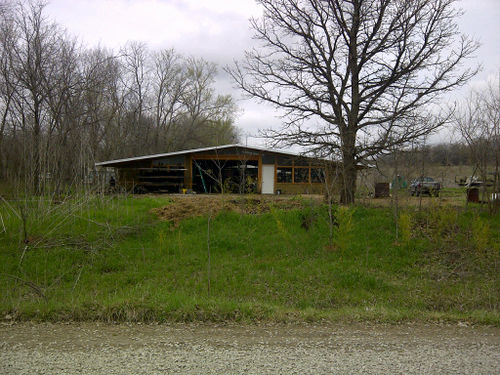
Our building site had several pieces of farm equipment sitting around. It also had a couple of old hay bales on it. Some experimental CEB columns had been built about 3-4' high and were protected by a 24'x24' assembled prototype roof. The area not covered by the roof was completely over-grown with weedy "biomass" and left-over materials from the column-building project turned up around the area too. Then when we laid out an approximate footprint for the workshop, there was one large tree and several smaller ones that hung dangerously over the prospective workshop site. All this needed to be cleared before we could begin the actual foundation work. There was so much work to do that we divided it into separate tasks.
Move the pre-existing roof
We decided to re-use this roof - which became a quite a project in and of itself. How we did this is covered on the Mill Shed page.
Move Large Pieces of Farm Equipment
Collect equipment and supplies needed
- Hedge clippers
- machete
- pruners
- Life-Trac tractor
Steps to follow
- Locate and identify pieces of equipment to be moved.
- Use hand tools to cut down weedy growth around each piece.
- Designate a place on farm to use each piece - or at least designate an out-of-the-way storage area for them.
- Use Life-Trac to transport items to their designated resting places.
Move old hay bales
Collect equipment and supplies needed
- Hedge clippers
- machete
- pruners
- Life-Trac tractor with hay pole attachment
Steps to follow
- Locate old hay bales on the workshop site.
- Use hand tools to cut down weedy growth around them.
- Designate a place on farm to use old hay bales -we decided that they might be useful for mulch in the garden or orchard area.
- Use Life-Trac to transport hay bales to a resting place near their prospective use areas.
Move building debris, etc.
Collect equipment and supplies needed
- Hedge clippers
- machete
- pruners
- Wheelbarrow
Steps to follow
- Use hand tools to cut down weedy growth and locate debris to be moved.
- Identify types of debris - i.e. old tires, reusable plastic, metal items, etc.
- Designate places for storage of each type of debris.
- Use wheelbarrow to transport debris to its resting places.
Remove overhanging trees
Collect equipment and supplies needed
- Chain Saw
- large Pruners
- hand pruners
- Life-Trac with bucket
- Pick-up truck
Steps to follow
- Designate trees for removal
- Designate location for disposal of debris
- Usable lumber sections - by mill shed
- Canopy pieces - we put this material across the farm and set the chipper near it - maybe we'll chip it into some mulch.
- Use the Chain Saw to cut down the trees - one at a time.
- Remove branches as needed for access to trunk
- Fell the tree to lie in convenient working location
- Cut branches at the main forks until millable lumber is all that remains
- Cut forks off the branches with pruners (and chain saw if necessary) to hand-manageable size.
- Chain saw branches to hand-manageable size. eut Transport pieces by foot or power to deposit site
- Load leafy materials and smaller branches onto Pickup for transport to chipping/deposit area.
- Cut millable trunks into as long sections as are manageable.
- Use Life-Trac bucket to transport millable sections to drying site near the mill shed.
Demolish Experimental Columns
Collect equipment and supplies needed
- Life-Trac with bucket
- Life-Trac with fork
Steps to follow
- Designate storage location for concrete pads and deposit site for CEB bricks.
- Push CEB's off concrete pads with Life-Trac bucket.
- Deposit CEB's in low area of foundation site and compact by running over them a couple of times.
- Pick up the concrete pads with fork - it took us one helper on the ground with a lever to get them properly set on the tines for lifting and transport.
- Transport and deposit the slabs in their resting place. We chose a place not too far away so we could get them back for recyling into part of our loading dock.
- Pick up
Laying out the building site
We set up a plan for doing this work ourselves, but we ran short of time and hired a professional to come and do the excavation including leveling the site, digging the pad foundation holes, and spreading the stone foundation material. Nevertheless, we did have to stake out the excavation site and locate the holes to dig out. Here's a quick way to get the first staking done and be sure that it is square.
Workshop
Collect equipment and supplies needed
- Blueprint of site plan
- (2) 100’ Measuring tapes
- 4 3-4’ stakes
- Hammer
- Bright spray paint
- Choose a spot approximately 5 feet to the North and 5 feet to the West of the area to be excavated.
- Pound in a stake and spray paint the top foot or two of it.
- Measure due East a distance 10’ longer than the foundation width (total 67’).
- Place and paint another stake.
- Calculate a distance 10’ longer than the foundation length (total 83’).
- Calculate the diagonal measurement of the excavation site [Length(squared) x Width(squared) = Diagonal(squared)] (106'8").
- Measure due South from the Northwest stake the distance calculated in step 5.
- Set the second tape measure on the Northeast stake and measure the diagonal calculated in step 6 going Southwest.
- Set your third stake where the two measured lengths meet each other.
- Paint the stake.
- Measure due South from the Northeast stake the distance calculated in step 5.
- Set the second tape measure on the Northeast stake and measure the diagonal calculated in step 6 going Southwest.
- Set your fouth stake where the two measured lengths meet each other.
- Paint the stake.
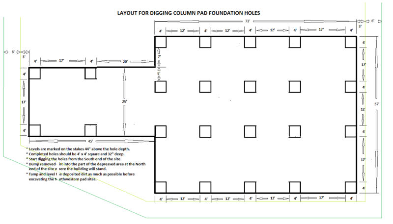
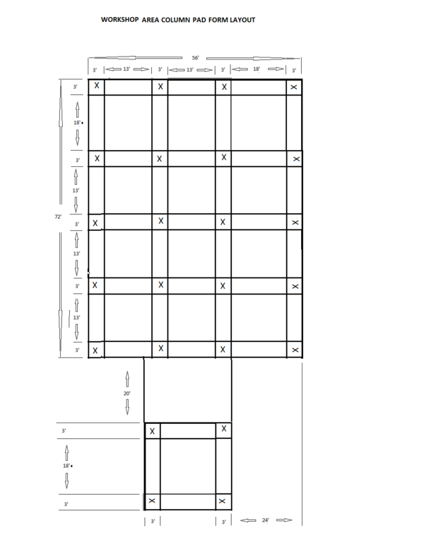
Here is a drawing with dimensions for laying out site for excavation of the column pad holes. The green lines indicate where the storm drainage ditch is planned to run.
Additional delivery area and storage/equipment shed
(We set this area to the south of the workshop and lined it up with the first row of columns in from the West wall.)
Collect equipment and supplies needed
- Blueprint of site plan
- (2) 100’ Measuring tapes
- 4 3-4’ stakes
- Hammer
- Bright spray paint
- Measure 21’ to the West from the Southeast stake along the South excavation line.
- Set a stake there and paint it.
- Measure 11’ to the East from the Southwest stake along the South Excavation line.
- Set a stake there and paint it.[The distance between the stakes should be 10’ greater than the width of the storage shed foundation. (total 35’)]
- Calculate the combined distance of the delivery area and the storage shed foundation (total 45’).
- Calculate the diagonal measurement of this part of the site [Length(squared) x Width(squared) = Diagonal(squared)] (57').
- Measure the distance calculated in step 5 due South from the stake set in step 2.
- Set the second tape measure on the stake set in step 4 and measure the diagonal calculated in step 6 towards the Southwest.
- Set your third stake where the two measured lengths meet each other.
- Paint the stake.
- Measure the distance calculated in step 5 due South from the stake set in step 4.
- Set the second tape measure on the stake set in step 2 and measure the diagonal calculated in step 6 towards the Southeast.
- Set your fourth stake where the two measured lengths meet each other.
- Paint the stake.
Area for Drainage ditches around the workshop
We had pre-existing drainage channels to the West of the site and to the South of the site. Still, we considered it important to plan for grassy waterways to the North and West of our low-lying site to keep storm water drainage under control at the Factor E Farm site. Working from theory, we developed some possible plans. In consultation with the excavator, we changed some of them.
- Updates will follow.
Layout
Collect equipment and supplies needed
- Blueprint of site plan
- (2) 100’ Measuring tapes
- 4 3-4’ stakes
- Hammer
Steps:
- Extend the South (East/West) Supply Shed foundation excavation line an additional 5’ to the East.
- Move the painted Southeast Supply Shed stake to this mark.
- Extend the South (East/West) workshop foundation excavation line an additional 5’ to the East.
- Move the painted Southeast workshop stake to this mark.
- Extend the West (North/South) workshop foundation excavation line an additional 5’ to the North.
- Move the painted Northwest stake to this mark.
- Extend the East (North/South) workshop foundation excavation line an additional 5’ to the North.
- Extend the North (East/West) workshop foundation excavation lines an additional 5’ to the East.
- Move the painted Northeast stake to a point close to where the last two extensions would meet.
Setting the level for the workshop
(We designed our floor to be level on the East/West axis and slope slightly on the North/South axis).
Collect equipment and supplies needed
- Levels Blueprint of site plan
- Water level
- 1 Measuring tape
- 1 Permanent marker
- Use the Water level to determine the relative level difference between the Southeast stake and the Northeast stake.
- Write 'at grade' on the lower stake.
- Mark on the higher stake the difference from level for excavation.
- Use the Water level to determine the difference in level between the Northwest stake and the Northeast stake.
- Calculate the excavation level to be 6" lower than the grade level at the Northwest stake.
- Mark the stake.
- Use the Water level to determine the difference in level between the Southwest stake and the Southeast stake.
- Calculate the excavation level to be 6" lower than the grade level at the Southwest stake.
- Use the Water level to check that the excavation markings on the Northwest and Southwest stakes indicate they are on level.
The first draft plan looked like this, if you are interested. [Detailed stakeout of building plan]
Preparing footings and base
We designed footings for the concrete pads supporting our CEB columns to be 4'x4' wide and 3' deep. There are 20 columns in our workshop design and 4 columns in the storage/equipment shed. Locations for each of these footings have to be marked out - and then excavated - and then filled and compacted. We also put a 6" gravel base under the entire concrete floor.
Laying out the column pad hole sites
Collect equipment and supplies needed
- Blueprint of site plan
- (1) 100’ Measuring tape
- 40 stakes
- Hammer
- 800-1500 ft. (500 m.) string
- 1 pre-built column pad form
- 1 can marking paint (it will paint when it's turned up-side-down)
- Workshop Stake and string steps:
- Run a line from the NorthWest excavation stake to the NorthEast excavation stake.
- Choose a point along the line about 6' East of the NorthWest stake and place a stake.(This will be the North end of the North/South origin line.)
- Run a line from the SouthWest workshop excavation stake to the SouthEast workshop excavation stake.
- Set a stake along this line to match the one on the North side of the site.
- Set stakes along each line at intervals of 3', 13', 3', 13', 3', 18', and 3'. (Starting at the stakes set in steps 2 and 4, the distances will be 3', 16', 19', 32', 35', 53', and 56')
- Run a line from the NorthWest excavation stake to the SouthWest excavation stake.
- Choose a point along the line about 11' South of the NorthWest stake and place a stake.
- Run a line from the NorthEast excavation stake to the SouthEast excavation stake.
- Set a stake along this line to match the one on the West side of the site.
- Set stakes along each line at intervals of 3', 18', 3', 13', 3', 13', 3', 13' and 3'. (Starting at the stakes set in steps 6 and 8, the distances will be 3', 21', 24', 37', 40', 53', 56', 69' and 72')
- Run a string between the two stakes set in steps 7 and 9.
- Run East/West string lines from each stake set along the West line in step #10 to the corresponding stake set on the East line in that step.
- Run a string between the two stakes set in steps 2 and 4.
- Run North/South string lines from each stake set along the North line in step #5 to the corresponding stake set on the South lines in that step.
- Storage/Equipment Shed Stake and string steps:
- Run a line from the SouthWest Shed excavation stake to the SouthEast Shed excavation stake.
- Identify the two North/South lines that form the North/South row of shop columns 21' West of the East side of the shop.
- Extend those two lines to intersect with the line run just run in step 1.
- Place stakes at the intersection points. (These stakes should be 3' apart.)
- Measure 2l' and 24' along the South shed excavation line from the Eastern stake and place two stakes.
- Measure along the more Easterly of these two lines 20' from the South workshop pad string line.
- Place a stake here.
- Place three more stakes at intervals of 3', 18', and 3' to the South.
- Measure along the South foundation line to a point 14' East of the North/South origin line (set in steps 2 and 4 above) and set a stake.
- Run a line from this stake to the stake set 24' along the South shed excavation line in step 6.
- Place three more stakes at intervals of 3', 18', and 3' to the North of this stake. (The most northerly of these should be 20' South of the South workshop foundation line.
- Run lines between corresponding stakes to create a 24' square grid showing (4) 3'x3' column pad locations.
- Extend the East/West lines about 5' in each direction and move the outside stakes there - so they don't get lost during the excavation and stone laying. You will need them to set the pad forms in place.
- Painting steps:
- Lay the pre-built column pad form under one of the 3'x3' squares marked by the grid of strings.
- Use the marking paint to mark a square on the ground outside the wooden form.
- Repeat for each of the (20) 3'x3' squares on the workshop foundation and each of the (4)3'x3' squares on the Storage/Equipment shed foundation.
Excavating the column pad holes
Once the hole locations were marked, we needed to get the strings we had used to locate them out of the way of the excavator. But we also were going to need them marking the same locations when we placed the forms for the column pads on top of the foundation stone - which would completely hide them from view! So here is our solution.
Save the location markers
equipment needed
- 24 pieces of wooden scrap
- hammer
What to do
- Make sure that all the location-marking string stakes are firmly planted at least 5' outside the foundation's footprint.
- Untie the East end of an East/West marking string.
- Wind the string up on a piece of wooden scrap, following it across the excavation site, and set it next to the stake outside the foundation at the West end.
- Wind up all the East/West strings in the same manner.
- Untie the South end of the North/South marking strings that only mark the workshop foundation lines.
- Wind these strings up and set the ball next to the stakes outside the foundation at the North end.
- Untie the North ends and the East ends of the storage/equipment shed marking strings.
- Wind them up and set them by the stakes at the outside of the shed foundation on the South and the West.
Dig the holes We had a professional come in at this point and dig the marked hole sites.
We hope to do our own excavating on another project. I'll put in some thoughts about that, but first, let's look at some of the things we learned working (as amateurs) with a professional dirt moving contractor. It seems that an experienced back-hoe operator can do a pretty good job of digging our 4'x4'x3' holes!
- We laid out and marked 4'x4' squares, but many of the dug holes came out 6" or more wider in length and width than planned.
- And the first holes were dug the full 36" deep since we didn't communicate well that we only needed 32" of hole depth. (Since we put 6" of foundation gravel on the graded level and set the pad foundations 2" down into that layer, we only really needed 32" deep holes.)
The result was that it took more foundation stone than we originally planned for.
- We were able to limit the (financial) damage by catching the depth problem less than half-way through the digging.
- We rewrote the lay-out instructions to mark the holes with a smaller footprint - it's pretty easy to widen a hole that's too small to start with - but pretty near impossible to do the opposite!
- Now - about doing our own excavating:
- You could use a backhoe bucket on your Life-Trac -
- practice somewhere else first to get the hang of it!
- As mentioned, it's pretty easy to widen a hole that's too small to start with - but pretty near impossible to do the opposite!
- And you have to be careful when moving around the site to stay away from the edges of holes aready dug.
- You could use an auger on your Life-Trac to start the corners, loosen the soil, and get some of it up. Then finish with manual labor.
- If you don't have power equipment, digging foundations for a building this size would be a lengthy - and very labor intensive - project!
- You could use a backhoe bucket on your Life-Trac -
I'll put up a possible step-by-step for that.
Dispose of the excavated dirt Our professionals pushed the excess dirt off the foundation area to the North and the South where the ground could use some filling and it was out of the way of the project.
My step-by-step has you moving it as it is excavated.
However you do it, you can't move on to laying your foundation stone until the building site is level again!
Laying stone foundation
This part of our project was, again, completed by our friends with the heavy equipment (and a laser level)- which made short work of pushing around and compacting a large amount of stone. We learned more by observation than by doing it ourselves this time.
Supplies and equipment needed
- (20) 2"x2"x12" leveling stakes
- 300 ft. (100 m.) string
- hammer(s)
- tamper
- Water level
Steps to follow
- Start at one corner of the foundation area and locate a leveling stake a few inches outside the corner of the excavated pad hole.
- Drive it into the ground until its top is 6" above the graded level.
- Tie the string around the post as close as possible to the top.
- Locate a stake in the same way outside each foundation hole and at each corner of the building footprint.
- Run the string around the entire foundation site, wrapping it around each post so that it is pulled tight.
- As the gravel truck delivers it, push gravel into the holes and around them to the height of the string.
- Use the tamper to compact the gravel every 12" as you fill the holes if you are doing this manually.
- -Or- Drive the heavy truck over the gravel fill when it has been spread to compact it.
- Continue to fill holes and spread gravel over the site until the foundation stone is evenly spread and compacted to the height of the leveling stakes.
- Use the water level to check that the gravel is spread evenly over the site, dropping about 1/2" every 5' from East to West.
GOOD WORK! NOW YOU'RE READY TO SET THE COLUMN PAD FORMS AND PREPARE THEM FOR A CONCRETE POUR!
CEB Columns
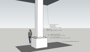
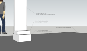
Compressed Earth Blocks (CEB) are at the heart of the ecological economy of this Workshop design. We use them to build the columns that support the roof as well as the walls to enclose the working space. For stability, the columns are constructed on a reinforced concrete pad laid on a stone footing. Instructions for preparing the site with adequate footings are on the Site Preparation Instructions page.
Our construction model is a modular one in order to use available people and time efficiently.
- We acquire supplies as our finances allow.
- We build the needed number of each sub-assembly in available time with available labor.
- An individual might build one unit at a time.
- Individuals with particular skills might work on completing a single step of the project.
- A couple of people available to work together on a project step will, most likely, be more time efficient.
- Several people working in assembly line fashion might complete an entire run of sub-assemblies efficiently.
- We construct with prebuilt assemblies.
In this column project, prebuilt assemblies to be used are:
- Concrete Forms
- Rebar Assemblies
- Roof Ties
Concrete Foundation Pads
Prebuilt Forms
Supplies and equipment needed
- (48) 2"x4"x7' stud beams
- (288) 3" deck screws
- tape measure
- pencil
- driver
- saw
- (optional) saw jig
Steps to do
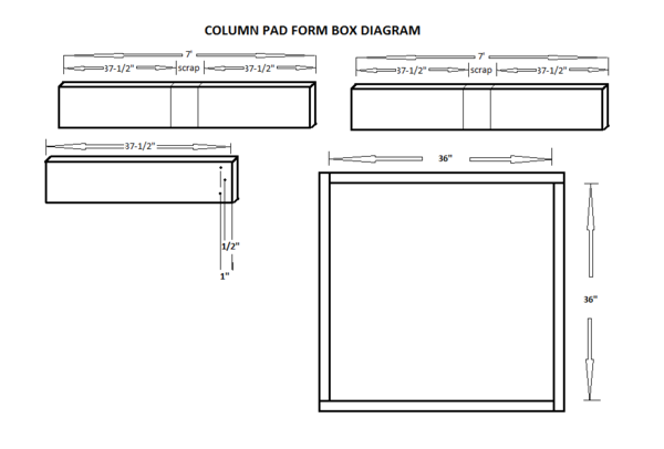
- Mark (2) beams at 37-1/2" from each end. (Alternatively, set up a jig with a stop 37-1/2" from the saw blade.)
- Cut four form side pieces.
- Butt two pieces at right angles and screw them together.
- Repeat step 3
- Butt and screw these two assemblies in a pinwheel style to create a form with an inside measurement of 3'x3'.
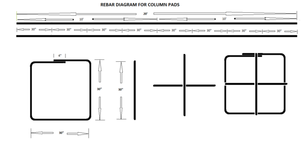
Prebuilt Rebar Assemblies
Supplies and equipment needed
- (18) 20' #4 rebars
- Rebar wire (if you don't have a welder)
- tape measure
- marker
- Rebar cutter
- Rebar bender (Shonda used a bench vice and a length of pipe for leverage - I'll ask him to document how that works!)
- metal saw
- spot welder
Steps to do
- Measure, mark, and cut 12 rebars into (24) 10' lengths.
- Measure, mark, and cut 6 rebars into (48) 30" lengths.
- Take a 10' piece of rebar and use four (4) bends to create a 30" square with an overlap on one side. (if you are wiring them rather than welding, make it an inch smaller so you can wire the cross pieces on.)
- Shonda says he used 2 inches of material between the vice and bending pipe. This gave him the same side length after bending as before.
- Since we wanted a side 30" long, he marked at 30" and positioned the bend pipe there.
- Then he clamped at 28" and did the bend.
- The end result was a 30" side with a 1 1/2 to 2" bend radius.
- Spot weld the overlapping ends to stabilize the shape. (Alternatively, wire the overlap together.)
- Spot weld one 30" piece one way across the square about half-way between the corners. (Alternatively, wire the two ends to the sides of the square)
- Spot weld another 30" piece the other way across the square.(Alternatively, wire the two ends to the sides of the square.)
Laying out the locations for the forms on top of the foundation stone
Once the form and rebar assemblies are built and the foundation stone is in place, the string site plan lay-out must be set up for placing the forms properly over their (now invisible) foundations. If you set your hole locating strings far enough out that the excavation didn't disturb them, this will be simple. It will be even easier if you rolled up your strings before the hole excavation got done and saved them. (See comments below about what happened to us!)
Collect equipment and supplies needed
- Blueprint of site plan
- 100' tape measure
- Pre-placed marking stakes around outside of foundation site.
- Rolled up pre-used string balls from foundation hole layout
Steps for Laying out Column Pad Form locations.
- Measure to check that all pre-placed marking stakes are properly positioned.
- If any are missing or misplaced, replace or reposition them as needed.
- Unroll and retie the strings to their corresponding stakes across the foundation site .
Here's what the layout over the stone should look like.
We had a great plan for this - we would set our stakes out first to mark the hole edges at 4'x4', save the strings and move the stakes in by 6" to 3'x3' for the setting the pad forms.
However, when we tried it in real life - Well...
- We lost a lot of our stakes during the excavation.
- We found the holes tended to come out bigger than we had intended them to be.
- And once the stone was laid over the site, we couldn't see where the foundation holes were located!
We wound up remeasuring and resetting most of the stakes for laying out the pad site grid.
- We dug stone out of two of corners to find the edges of the foundation holes.
- We remeasured and reset corner marking stakes inside those edges.
- We retriangulated with the diagonals to assure the foundation square.
- And we remeasured and reset stakes along all the edges.
So we've rewritten the foundation lay-out plans as they are currently posted. In the current version, we set the stakes at the 3'x3' points to start with so they don't need to be moved. We also emphasized setting them firmly - and safely outside the excavation area.
Setting the column pad forms
Collect equipment and supplies needed
- Supplies
- 24 Pre-built column pad forms
- 120 form stakes (we used 2"x2"x18" wooden stakes)
- Equipment
- Heavy Hammer(s)
- 4'spirit Level
- Water level
- tape measure
Steps to place Column Pad forms
- Choose one pad site along the East edge to be the reference pad. (The center of the East side works well.)
- Set a pre-built column pad form in place under the string lines with the inside of the forms under the strings.
- Drive two form stakes next to the outside of one side and one on each of the other three sides. They will need to sit deep enough that the tops of the stakes will be level with (or lower than) the top of the form.
- Level the form.
- Screw one of the stakes (on the side with two) to the side of the form so that the form sits 1/2" above the gravel level with the top of the stake level with (or lower than) the top of the form.
- Use the spirit level to set this side of the form level and screw it in position.
- Use the spirit level to set the opposite side of the form at the same level.
- Check the level on the other two sides and screw them in place.
- Use the water level to set another form in the East row of columns to be level with the reference pad.
- Repeat steps 2 through 5 to complete setting the forms in that row.
- Use the water level to set the level of the center form in the next row of columns (to the West) as a reference form for that row. It should be about 1-1/2" lower than the reference pad in the previous row of columns.
- Repeat steps 2 to 7 two more times.
- Repeat steps 2 to 5 again.
CEB Column Pads includes preparing rebar reinforcement assemblies, building concrete forms, and setting the forms in preparation for pouring concrete.
Basic column building
How to lay a brick: http://www.youtube.com/watch?v=lORIZ1shRIM
Preparing the top of the column for tying on the roof
Reinforced Concrete Floor
Forms and Concrete Work includes layouts for prefabricated rebar reinforcement assemblies specific to each configuration of slab specific to this workshop plan.
Electrical Power Lines
Electrical Power in the Workshop
OSE Roof Instructions
Our roof is modularly designed to take minimal time to put in place. Prebuilt wooden stringers are tied to the CEB columns with prebuilt assemblies put in place during the column construction. Then prebuilt 16'x16' frames are laid on top of them, glued and screwed to each other, and strapped to the stringers. Steel barn roofing attached to the roof frames provides protection from the weather. The finishing touch will be installation of clerestory framing and light panels to provide natural lighting to the interior of the workshop.
Pre-building the Roof Frames
Future Instructions
Forms and Concrete Work
Building CEB Columns
Enclosing the Workshop
CAD Room - Insulation, Raised Floor
Electrical Power in the Workshop
Hydraulic and Pneumatic Plumbing
Water Collection and Distribution
Storm Water Management
Loading Dock
Driveway/Parking Considerations
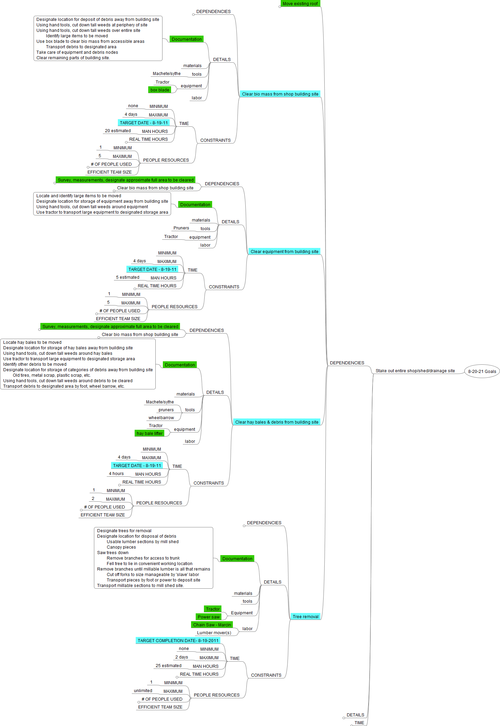
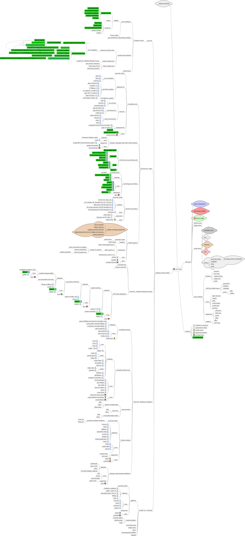
Construction Plan Mindmap
Full size here:[[1]]
Actual Mindmap file here (created with freemind) [[2]]
Design Notes
An overview of planning and implementation for 2011 here in northwestern Missouri can be followed on the Factor E Farm link.
A 12 cell (16'x16') workshop for prototyping and production runs of open source ecology machines was projected. During the design phase, one row and one column of cells were expanded to sit on 21' centers. The 21'x21' cell is now designated as the CAD Room.
Steps taken to recycle and use a roof structure built as a prototype are shown on the Mill Shed page.
Designs for a group habitation can be seen here. The one we're working on in the Fall of 2011 is shown on this page.
See also this posted prototypical small CEB Living Unit idea.
See also
Latest Shop Design
This shows the designs we are working with for building the shop and the hablab. Placement of other structures currently on the property are roughly shown by plain shapes.
Follow submissions from original workshop concept of A 12 cell (16'x16') workshop for prototyping and production runs of open source ecology machines to current project design below.
Expand Shop
- Moved both last rows of columns out 7.5 feet
- Very moderate cost for 500 additional square feet of space
- Simplifies roof plan.
Storage/Equipment shed on south end
Between the shop and the berm
Equipment Room
Build an equipment room in the storage shed.
This will keeps the noise of the compressor, generator, hydraulic pump, and such away from the shop. Will also provide storage for smaller parts. Piping and conduits carry power in various forms into the shop.
Driveway
Improve and expand the driveway to be smoother, wider, and double-access (pull-through) and have designated parking spots.
Loading Dock
Add a loading dock for easy access to truck bed level deliveries
Heating
Our climate will require heating areas designed for habitation and work during approximately 5-6 months of the year. Possible solutions might include
Masonry Stove
http://dnr.mo.gov/pubs/pub781.pdf
Hydraulic Power
We may install a central hydraulic system
Technical Notes
Roof
Use 2x6 for roof boxes
2x6's cost *half* of what 2x10's cost. We're spending almost $3000 on lumber. Can we save $1500?
This calculator externally:
Indicates that 2x6's on 24" centers can be used for our roof box spans easily if our snow load is less than 10 pounds per square foot (about a foot of snow), and probably are even okay for 10 pounds per square foot.
Note, however, that this table lists DeKalb county design snow load at 20psf and this article from a Webster county extension agent recommends 25psf total load. See also ASCE snow load calculations including ridge drift at fig 7-8.
It is my judgement that at least shifting to 2x8's to save cost would be worthwhile. 2 x 6's will work fine, the vast majority of structures use them.
The advantage is cost of 75 cent per square foot cost of roofing structure - ready to accept roofing such as barn metal. Compare this to about 2-3 times that muss for a truss system for a 64 foot span (4' overhangs on each side), ready to accept roofing metal. See truss prices.
Roof Tie
The use of Simpson Strong Tie model 2.5 can bind the roof panels to the rafter boards in such a way as to bind the roof to the rafters. We will use 100 of them, tying all of the edges and middles of the roof boxes to the rafters.
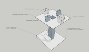
An early idea for tying roof to supporting CEB columns
Stringers
(2x6 design for the stringers which support the roof boxes may need to be beefed up. See below.) The first stringer pair has been fabricated and will be load-tested soon.
First Stringer Prototype:
strength analysis
Where columns are on 16x16ft centers, ~256 sq ft of roof is supported on each column, i.e 2560 to 6400 lb (based on assumed total load from 10 psf to 25 psf). This amount of load is transferred from roof boxes to columns through East-West stringers and North-South purlins. If stringers and purlins share the load equally, each 16-foot span must carry 1280 to 3200 lb. Worst case span/load is over CAD room where columns are on 21ft centers rather than 16ft.
Wood beam design theory here. Typical design formulas will tell us to use deep beams for adequate stiffness: otherwise the beam will bend "too much" (1/2" to 1" at midspan according to common design rules). Bending too much might damage the roof covering but is not a dangerous collapse condition. Three other important design criteria are
- bearing: will the wood crush where it bears on the support (this is a concern not only where the beams bear on the columns but also where boxes rest on purlins)
- shear: will the beam shear apart near its supporting pier
- bending strength: will the tension in the bottom edge of the beam tear it apart
Either of the last two failures will cause immediate structural collapse.
Truss option
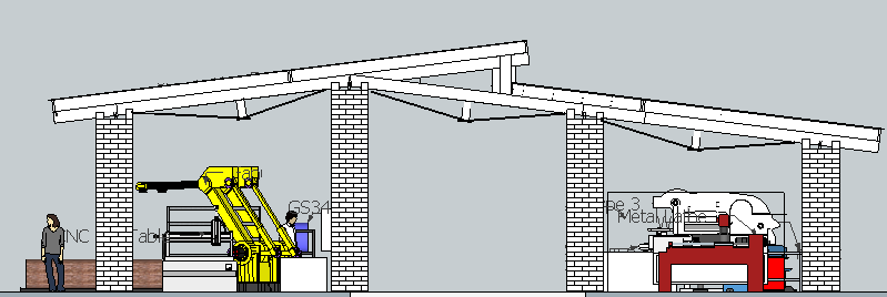
A simple inverted kingpost truss using steel-bar tension members, added to the 2x6 stringer design, may work well.
I-joist option
According to this guide I estimate a 12-inch deep PRI-50 IJoist would carry 3200 lb @ 1" deflection (L/180) across a 16ft span.
Very loose cost estimate: $2.00/linear foot. Approx 375 linear ft in 5 stringer sets + 280 linear feet in 16 purlin beams = $1310.
Foundations
The site is a heavy clay soil with a calculated bearing capability of between 1000 and 4000 pounds per square foot. The foundation design goal is to bring the building static load below 1000 PSF, so that the possible live load (gantry crane loaded, snow on the roof) even doubling the load will keep the foundation pressure beneath 2000 PSF.
Earth Compaction
See Earth Compaction
Components
- Roof sections
- Roofing materials - Chris
- Stringers for workshop -
Budgetary Considerations
See Factor e Farm Infrastructure Buildout 2011 Budget See Construction 2011 Fuel Budget
- Rebar - OSE_Shop_2011_Rebar_Acquisition
- Bulldozing and excavation - $2-3k
- Cement trucks -
Actual
- 4 Milwaukee cordless drills – total dollars 407
- Roof metal - 136 panels, 17' long (3' widths) - 108 for workshop, 22 for material shed, and 6 extra + flashing for clerestory + screws + flashing closure – total dollars 5871
- 2x6 lumber,16' long, 6.60 - total 396 pieces - total dollars 2802
- Glue, #25 star driver bits, 3" star bit screws, 2 glue guns, furring strips, 2 tie downs – total dollars 299
- Trailer rental for lumber – total dollars 47
- Gravel receipt for OSE Shop 2011 - 5000 sq ft of 6" deep plus 4x4x3' pillar bases - $2703 (Shop Gravel Receipt)
Tools and Equipment Purchases
- 4 Milwaukee cordless drills - total dollars 407
- #25 star driver bits
- 2 glue guns
- 2 tie downs
- Trailer rental for lumber – total dollars 47
- Wheel barrow, masonry hoe - total dollars 68
Sources
OSE_Shop_2011_Rebar_Acquisition Amazon.com Home Depot - St. Joseph Menard's - St. Joseph
Out-sourced Expenses
- Bulldozing and excavation - 2-3k
- Cement trucks -
Links
- Workshop - Layout of OSE workshop for production purposes
