Open Source Lathe
- HABITAT: CEB Press - Sawmill - Living Machines - Modular Housing Units
- AGROECOLOGY: LifeTrac Multi Purpose Tractor - MicroTrac - Power Cube - Agricultural Spader - Agricultural Microcombine - Hammer Mill - Well Drilling Rig - Organoponic Raised Bed Gardening - Orchard and Nursery - Modular Greenhouse Units - Bakery - Dairy - Energy Food Bars - Freeze Dried Fruit Powders
- ENERGY: Pyrolysis Oil - Babington Burner - Solar Combined Heat Power System - Steam Engine Construction Set - Solar Turbine - Electric Motors/Generators - Inverters & Grid Intertie - Batteries
- FLEXIBLE INDUSTRY: Lathe - Torch Table - Multimachine & Flex Fab - Plastic Extrusion & Molding - Metal Casting and Extrusion
- TRANSPORT: Open Source Car
- MATERIALS: Bioplastics
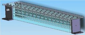
Here we are showing the details for fabricating a high-performance (2/1000" accuracy), high power (20 hp) lathe. It will be powered from the hydraulic take-off from a tractor - LifeTrac. The design follows that of the Multimachine. Instead of an engine block as the basic structural unit, we'll be using a concrete bed with metal mounting plates. The advantage of this route is that we are avoiding the necessity of sourcing and boring out the engine block. Moreover, the concrete bed will be its own lathe mount structure.
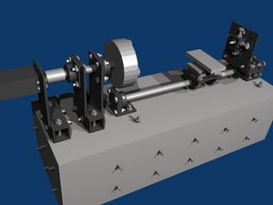
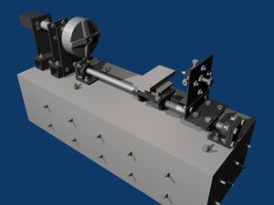
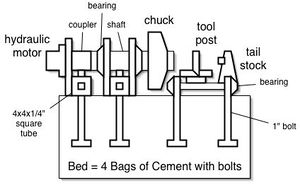
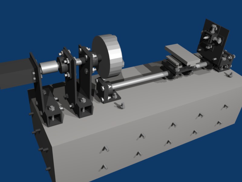
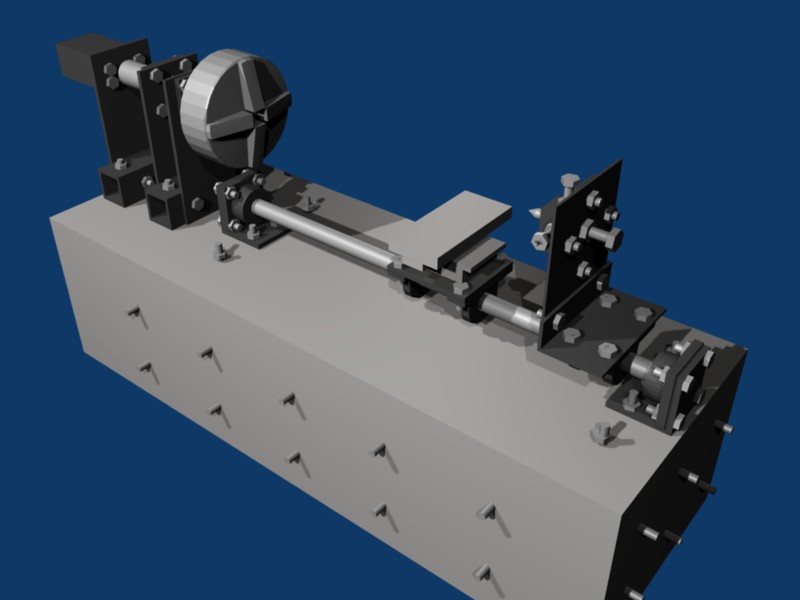
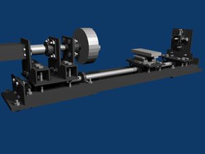
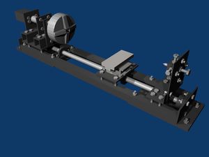
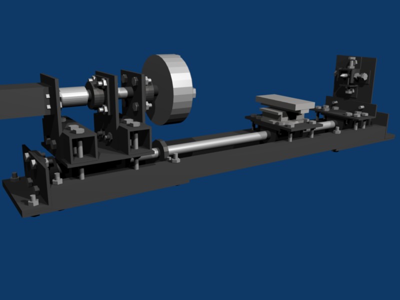
This route allows for the construction of a lathe from stock parts - metal plate, shaft, coupler, bearings, bolts, and concrete. We add a cross slide and chuck on top of that, and use a hollow shaft tube for workpiece feed-through:
Design Rationale
- High power, simple design
- OSE Specifications are met via low cost for replication; a transparent, open source development process; open documentation; product evolution infrastructure
- External power source
- Interchangeable motor - part of LifeTrac infrastructure, motor can be coupled to many different devices
- Hydraulic motor provides high power and torque with full speed control via a flow control valve
- Basic design:
- Romig type lathe bed made of concrete(see below)
- Metal plates are used to attach functional parts of lathe to concrete bed
- Large hollow shaft attached to bearing blocks on plates
- Two bearings with bearing clamps holding bearings in place:
- Clamps as such hold the chuck in place
- Cross slide is mounted on another plate
- Tail stock?
Specifications
Fabrication and Cost
- Ease and low cost of fabrication is the primary goal, as a high-performance lathe is perhaps the most important tool in a workshop
- Construction consists of a stable concrete bed
- Cost is that of 4 bags of concrete for the bed, chuck, cross slide, and
- Motor cost is included in LifeTrac infrastructure
- Motor coupler to lathe shaft is machined
- Commercial chck is the main cost
- XY table constitutes a cross slide
- Tool post is fabricated
- 2" shaft constitutes a mounting surface for an xy table and for tail stock
- Feed-through shaft is present, but is only 1 foot deep
- Cheap 2 15/16" bearing
Specifications
- 12" lathe
- 1/1000" accuracy via bearing tolerance and chuck tolerance
- Heavy duty axial thrust acceptable, as determined by 3" shaft and bearings
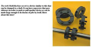
- Radial thrust determined by set screws on 2 bearings, with 2 extra full split collars
Design
Motor
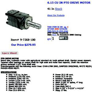
Brute 20 horse of turning power is provided by a hydraulic motor powered by LifeTrac
Shaft Coupler from motor to shaft
Bearings
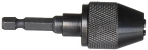
Chuck
We will fabricate a chuck from a 1" steel pate, as in:
- http://www.wttool.com/product-exec/product_id/13768?utm_medium=cpc&utm_source=froog
- http://www.grizzly.com/catalog/2009/Main/590
- http://www.google.com/products?q=lathe+chuck+4+jaw+12&hl=en&scoring=p
Slide
For the lathe to be able to handle large work pieces, the slide itself - which holds the tool post.
- Milling Drilling Slide $90
- http://www.google.com/products?q=%22cross+slide%22+-jewelry+-shoes&hl=en&scoring=p&sa=N&lnk=next&start=100
- http://www.shop.com/Cross_Slide_Vises-34856820-45455382-p!.shtml?sourceid=298
- http://www.harborfreight.com/cpi/ctaf/displayitem.taf?Itemnumber=32997&zmam=33951326&zmas=12&zmac=112&zmap=32997
Tool Post
The tool post will have to mount securely to the cross slide.
3D Design
Pictures
Design 2
The second design is based on feedback that the slide shaft could not be aligned with the spindle, so we combined the shaft and slide, and joined them with 1/2" cold rolled square tube. The bolts from each section adjust the level to keep anything from coming loose and add extra support.
3D Design
Pictures
Bill of Materials
- Romig bed lathe type - about 9 bags concrete mix
- Foundation frame materials:
- 74x20" long side boards, x 2
- 26x20" short side boards, x 2
- 27x75" bottom board
- 28x3" top boards to hold bolts, x 4
- 12" long bolts, x 12
- Concrete mix
- 4x4x1/2" square tube 12" long, x 2
- 3x6x1/2" L angle 9" long
- 6x6x1/2" L angle 6" long, x 2
- 3x3x1/2" L angle 3" long, x 4
- 8x18x1/2" plate, x 3
- 12x10x1/2" plate - tail stock holder
- 8x9x1/2" plate - tool post slide holder
- 1-7/8" shaft 17" long
- 1-7/8" shaft 50" long
- 1-7/8" 4 bolt bearings with lock collar, x 4
- 1-7/8" Pillow block bearings with lock collar, x 4
- Milling Drilling Slide
- 4 jaw Chuck
- plate for mounting chuck
- attachments for chuck plate
- PTO Motor
- Motor to 1-7/8" shaft coupler
- 12" long bolts, with nuts and lock washers, x 12
- 16 4 bolt bearing bolts, with nuts and lock washers
- 4 pillow block bearing bolts, with nuts and lock washers
- 4 motor bolts, with nuts and lock washers
- 4 drilling milling slide bolts, with nuts and lock washers
- 6 plate bolts, with nuts and lock washers
- 4 tail stock L angle holding bolts, with nuts and lock washers
- 4 tail stock adjuster bolts, with nuts and lock washers
- 1 large tail stock bolt, with 2 large washers, lock washers, and nuts
- tool post
- 77" long rebar, x 3
- 29" long rebar, x 5
- 31-1/3' of rebar total
Sourcing and prices
Steel @ $0.75 per pound.
| Part(s) | Total Weight | Price |
|---|---|---|
| 4x4x1/2" square tube 12" long, x 3 | 64.89 | $48.67 |
| 6x6x1/2" L angle 6" long, x 2 | 19.6 lbs | $14.70 |
| 3x3x1/2" L angle 3" long, x 4 | 9.4 lbs | $7.05 |
| 8x18x1/2" plate, x 3 | 61.2 lbs | $45.90 |
| 8x12x1/2" plate | 13.6 lbs | $10.20 |
| 8x9x1/4" plate | 5.1 lbs | $3.825 |
| 1-7/8" shaft 17" long | 13.36 lbs | $10.02 |
| 1-7/8" shaft 50" long | 39.29 lbs | $29.47 |
| Total | 226.44 lbs | $169.83 |
| Part(s) | Price |
|---|---|
| 1-7/8" 4 bolt bearings with lock collar, x 4 | $67.80 |
| 1-7/8" Pillow block bearings with lock collar, x 4 | $67.80 |
| Milling Drilling Slide | $89.95 |
| 4 jaw Chuck | $119.95 + $44 shipping = $163.95 |
| PTO motor | $279.95 |
| Tool post | $125 |
| Total | $794.45 |
Total for steel and parts: $963.73
Implementation
Frame Materials
Build a wood frame to pour concrete into for the foundation.
- 75x16" long side boards, x 2
- 26x16" short side boards, x 2
- 96x48" bottom base board
- 28x3" top boards to hold bolts, x 4
- 2x4" boards 96" long, x 2
- 12" long bolts, x 12
- Concrete mix
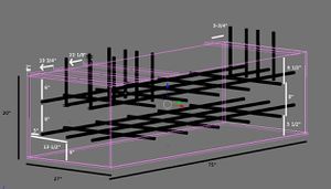
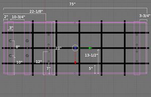
- Put the frame together according to the diagrams. Attach the long side boards to the sides of the short side boards to make a rectangular frame, then attach it to the top of the bottom base board. Cut the 2x4's and attach them to the base board around the bottom sides of the frame to keep it from warping from the concrete.
- Drill holes for rebar according to diagrams. Put the rebar through the holes.
- Drill holes for the bolts in the top boards and put the 12" bolts in. Put nuts on the bolts and tighten them so that the first 4 bolts for the spindle hang 7" below the board and the others hang 10" below. Then attach the boards to the top of the frame according to the diagram.
- Mix and pour the concrete into the frame. Smooth the concrete out along the top of the frame.
- Wait for the concrete to dry.
- Remove the wood frame.
Build the spindle.
- Drill holes in the square tubes and plates.
- Attach the tubes to the foundation, then the plates to the tubes, and the 4 bolt bearings and motor to the plates.
- Put the spindle shaft through the bearings and use the coupler to attach it to the motor shaft.
- Attach the chuck plate to the shaft, then the chuck to the chuck plate.
- Attach the hydraulic hoses to the motor.
Build the slide.
- Drill holes in the L angles, and plates.
- Attach the 4 bolt bearings to the L angles.
- Put the pillow blocks on the shaft, then put the shaft into the 4 bolt bearings to make the shaft assembly.
- Attach the shaft assembly to the foundation.
- Attach the Mill Drill slide plate to the first 2 pillow blocks, then attach the Milling Drilling slide to the plate.
- Attach the large L angle to the second pillow blocks, the plate to the large L angle, the L angles to the plate, and put all the bolts through the holes.
Lathe Tools
Links
- Similar lathes
- the Open Lathe Project wiki
- single shaft slide lathe - Drummond All Round Utility Lathe
- http://www.lathes.co.uk/scope/
- http://www.lathes.co.uk/kneller/index.html
- 3D printed Lathe
- Other lathe stuff
- http://www.sherline.com/4400pg.htm
- openlathe group
- Build a Complete Metalworking Shop from Scrap! The Legendary Series of Machine Tool Construction Manuals - https://gingerybookstore.com/MetalWorkingShopFromScrapSeries.html
- http://www.backyardmetalcasting.com/lathe1.html
- Homebuilt lathe - http://silent1.home.netcom.com/HomebuiltLathe.htm
- Fonly lathe - http://www.btinternet.com/~two.mm/articles/fonly/fonlypt1b.htm
- Light duty toy lathe - http://www.instructables.com/id/100-Homemade-Lathe/?ALLSTEPS
- Modulate https://blog.freecad.org/2025/11/21/forged-in-freecad-the-modulathe-v2/
