CEB Press/Manufacturing Instructions/Roller guides: Difference between revisions
Jump to navigation
Jump to search
(→=Nuts:) |
|||
| Line 36: | Line 36: | ||
== Fabrication Steps == | == Fabrication Steps == | ||
Main plate: | ===Main plate:=== | ||
*Punch 1/2” diameter holes in 1/2”x3”x12” plate. (3 holes) See diagram. | *Punch 1/2” diameter holes in 1/2”x3”x12” plate. (3 holes) See diagram. | ||
*Put 1/2” bolt thru the center hole and weld it in place. | *Put 1/2” bolt thru the center hole and weld it in place. | ||
Spacer plates: | ===Spacer plates:=== | ||
*Punch a hole for the bolt welded to main plate. This should be centered horizontally, and placed vertically so that the plate doesn't stick out from the main plate. | *Punch a hole for the bolt welded to main plate. This should be centered horizontally, and placed vertically so that the plate doesn't stick out from the main plate. | ||
12mm bolts: | ===12mm bolts:=== | ||
*Grind off the top of the bolts so that the head is 1/4” thick or less. (This is so that the bolts will not be touching the drawer as it slides in and out.) | *Grind off the top of the bolts so that the head is 1/4” thick or less. (This is so that the bolts will not be touching the drawer as it slides in and out.) | ||
Assembly: | ===Assembly:=== | ||
*On the 12mm bolts, place, in the following order, the V groove bearings, one lock washer, the main plate, one lock washer, the 12mm nut. The bearings should be on the side of the 1/2” bolt head. | *On the 12mm bolts, place, in the following order, the V groove bearings, one lock washer, the main plate, one lock washer, the 12mm nut. The bearings should be on the side of the 1/2” bolt head. | ||
*Place one of these on each end of the main plate. | *Place one of these on each end of the main plate. | ||
Revision as of 21:18, 23 August 2011
| |||||||||||||||||||||||||
See also CEB Press Build Instructions See also CEB Press/Bill of Materials
Tools Required
- Hole punch or drill with 1/2” bit
- Welder
- Angle Grinder
Materials Required
You need 2 roller guides. Each one requires the following:
Steel:
- 1/2”x3”x12” plate (1)
- Spacer plate (1) (One roller guide will use a 3/8" thick plate, and the other will use a 1/2" plate)(these can be scrap, but need to be smaller than 3”x9.5”)
Bolts:
- 1/2”x2” bolt (1)
- 12mm x 50mm bolts (2)
Nuts:
- 1/2” nut (1)
- 12mm nuts (2)
Washers:
- 1/2” washer (1)
- 1/2” lock washer (1)
- 12mm lock washers (4)
Bearings:
- V Groove bearing 12mm Buy
Diagrams
Fabrication Steps
Main plate:
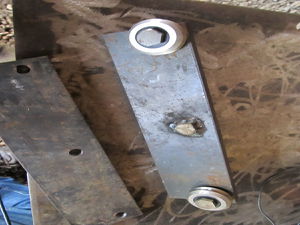
- Punch 1/2” diameter holes in 1/2”x3”x12” plate. (3 holes) See diagram.
- Put 1/2” bolt thru the center hole and weld it in place.
Spacer plates:
- Punch a hole for the bolt welded to main plate. This should be centered horizontally, and placed vertically so that the plate doesn't stick out from the main plate.
12mm bolts:
- Grind off the top of the bolts so that the head is 1/4” thick or less. (This is so that the bolts will not be touching the drawer as it slides in and out.)
Assembly:
- On the 12mm bolts, place, in the following order, the V groove bearings, one lock washer, the main plate, one lock washer, the 12mm nut. The bearings should be on the side of the 1/2” bolt head.
- Place one of these on each end of the main plate.
- Tighten them down.
- On the side with the 1/2” bolt threads, place the spacer plate** on the bolt.
- The two roller guides will be identical, except for that one will have a 1/2” spacer plate, and the other will have a 3/8” spacer plate (this is to properly space the guides to the rails on the drawers).
