CEB Press/Manufacturing Instructions/Main Frame Preparation
| |||||||||||||||||||||||||
![]() Warning: The documentation for the CEB Press is undergoing a thorough overhaul. CAD models and written directions are presently obsolete. For more information, see Talk:CEB_Press#Documentation_overhaul_in_progress. When the models, specifications and text on this article have been thoroughly reviewed, updated when necessary, and confirmed as whole and accurate, this warning may be removed.
Warning: The documentation for the CEB Press is undergoing a thorough overhaul. CAD models and written directions are presently obsolete. For more information, see Talk:CEB_Press#Documentation_overhaul_in_progress. When the models, specifications and text on this article have been thoroughly reviewed, updated when necessary, and confirmed as whole and accurate, this warning may be removed.
The following steps can be done in any order before beginning the assembly of the main frame.
Tools Required
- Welder
- Torch
- Punch with 3/4" dies
- Angle Grinder
- Big square
- Speed square
Materials Required
Steel
- 6” Heavy (7/16”) U-Channel- (246.5" Monster CEB) (226.5" Normal CEB)
- A- (53” for Monster)(43" for normal) (2); Vertical Members
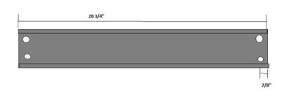
- B- 20 3/4” (4); Horizontal Members
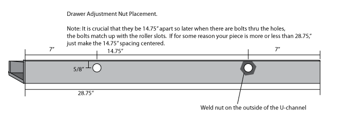
- C- 28 3/4” (2); Drawer Members
- 3” U-Channel: 3" total: 1.5” (2); Thin cylinder Spacers
- 1” Pipe: 3" total: 1.5” (2); Thin cylinder Spacers
- 1/4”x1” Flatbar: (13” for Monster)(9" for normal) (1); Magnet holder
- 3/8” Rebar: 7" total: 3.5” (2); Sensor Holders
Nuts and Bolts
Note: we suggest using steel nuts, because these will be welded, and the galvanized nuts release toxic gases when welded. You can use galvanized instead if necessary, but its not recommended.
- 3/4" Steel Nuts (4 normal CEB, 8 monster CEB)
- Drawer members: (2)
- Thin cylinder supports: (2)
- Monster CEB only: (4) Drawer adjuster bolts
- 3/4" Galvanized Nuts (7)
- Magnet holder (1)
- Drawer adjusters (4)
- Sensor holders (2)
- 3/4” Threaded Rod: (20.75” total normal ceb) (35.75" total monster ceb)
- Magnet holder: 1.25" (1)
- Sensor holders: 3.5" (2)
- Thin cylinder support bolts: 6.25" (2)
- Monster CEB only: Drawer adjuster bolts: 3.75" (4)
- 3/4"x2.5" Bolts (Normal CEB: 6, Monster: 2)
- Wide cylinder supports: (2)
- Normal only: Drawer adjuster bolts (4)
Diagrams
The holes in the horizontal members:
The holes in the drawer members:

Fabrication Instructions
Prepare the horizontal members(B), vertical members (A) and the drawer members (C)
All need holes marked. The drawer members need holes torched, and nuts welded to them. The vertical members need holes punched, nuts welded, and holes torched.
Marking
- Mark the holes in the horizontal members and drawer members as shown in the diagram above. Center punch them.
DON'T PUNCH THEM! They will be mag-drilled later.
Punching
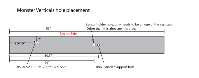
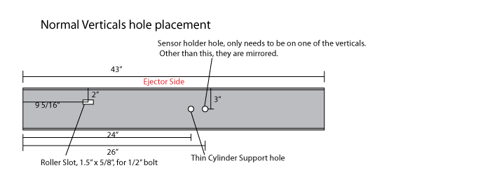
- See the diagrams for the vertical members hole locations, as they vary between the "normal" and "monster" CEB's. They will need to be mirror images, but only one vertical will have the sensor hole.
Torching
Vertical Members
The roller slots need to be torched. This is where the rollers bolt to the frame. See diagram.
- The center of them is located 9 5/16" away from the top of the machine, 2 inches in from one side of the U-Channel of the vertical members. This side must be the side which ejects the bricks. Label it so. Keep in mind the vertical members are mirror images of eachother, so don't make the same holes.
- They are to be 1.5" tall, and 5/8" wide.
- Grind away all slag.
Drawer Members
- Torch holes for 3/4" bolts as shown in the diagram.
- Grind away the slag.
Welding
Drawer Members
- Weld 3/4" nuts to the outside of the U channel where the holes are torched.
- Weld it with a bolt coming thru the other side so it protects the threads and so you know the nut won't get off center.
- Grind away any spatter between the bolts.
Monster only: Adjustment bolts
- Make (4) 3/4" x 3.5" bolts using 3.75" threaded rod and steel nuts. See Making Bolts.
Assembly
- For the Drawer Members, Put the nuts and bolts in thru the U-channel and welded nut, as shown in the image.
Prepare the thin cylinder supports
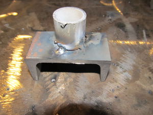
- Weld some 3/4" ID pipe (3/4" to 1") to the 3" U-channel, in the center. 4-8 good tacks is sufficient.
- Make 2 6" long 3/4" bolts, by using a nut and 6.25" of threaded rod. See Making Bolts.
Prepare the magnet holder
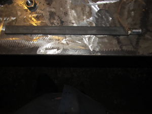
- Shield the threaded rod (1.25") from spatter by putting 2 nuts on it.
- Prop up the 1/4"x1"x(13" for monster)(9" for normal) flatbar so it's level with the center of the threaded rod, ensuring they are parallel.
- Weld the two together and remove one nut, leaving one in place. Be careful that it doesn't warp out of square.
Prepare the sensor holders
You will need one later which attaches to the arms, so it's suggested you make two. Its also included in the above materials.
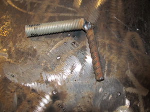
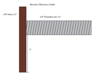
- For normal, weld 3.5" of rebar to 3.5" of threaded rod at a right angle, taking care to protect the threads from spatter. See image on right.
- For monster, make one sensor holder like above, and one as shown on the left.
Thread a galvanized nut onto each.

